Homebrew Frequency Counter
Using PLJ-8LED Display
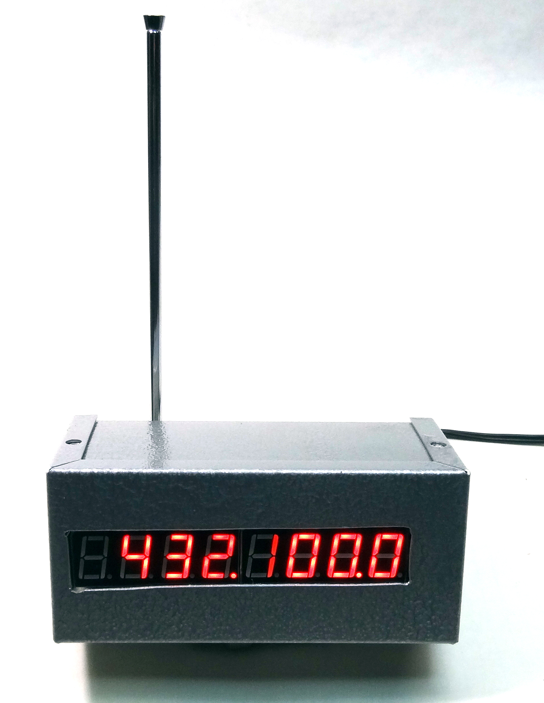
An article appeared in the December 2020/January 2021 #379 issue of Electric Radio Magazine showing accessories for the shack. One item was a frequency counter and an RF sampler. Seeing this article I purchased one of the PLJ-8LED displays via Amazon. There are many different suppliers but this particular one was around $18 prime free delivery. This is an 8 digit display that will count at least to the 440Mhz band as you can see in the opening photo the counter is displaying 432.100 Mhz from my handheld. It is very sensitive at that frequency and displayed accurately at a few feet away running 1 watt with just a short whip antenna.
I used a small mini-box Bud CU-3004-A 5"x2.25"x2.25" which was just wide enough to snugly fit the display. The display is 8 digits and has two input buttons on the right side. These did not lend themselves to be usable on the front panel as they are recessed and would be hard to get to. So I paralleled the two push button switches and mounted two equivalent switches on the back panel.
I was not real happy with the resistor values that the author used in the Electric Radio article. In that case it was a 50K/68K divider, basically 2:1. At 1500 watts at 50 ohms with a perfect match voltages can reach 250V or more. Since the divider he proposed would only reduce this by half or so depending on the input impedance of the display I felt this could damage it at high levels. In my circuit I use a 100:1 100K/1K divider and as a safety measure back to back zeners which would limit the maximum voltage to less than 5V. The display is very sensitive and even with this circuit a whip antenna connected to the box reads the frequency of my hand-held on VHF/UHF and on HF I can read fine down to 5 watts, the minimum of my rigs output.
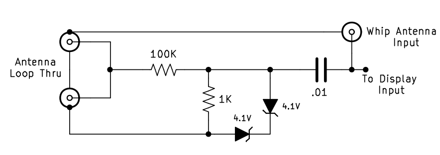 My RF Sample Circuit
The display has four mounting holes in the corners but it was such a nice fit in the mini-box that I decided to forgo the screws and instead I used hot glue on the four corners. Hot glue is nice because in keeps it in place and if you ever do have to remove it you can. Here are several more photos of the project. The box was sprayed with grey hammertone paint. The opening was marked and cut with a sabre saw and filed to size. It is not exacting but looks OK.
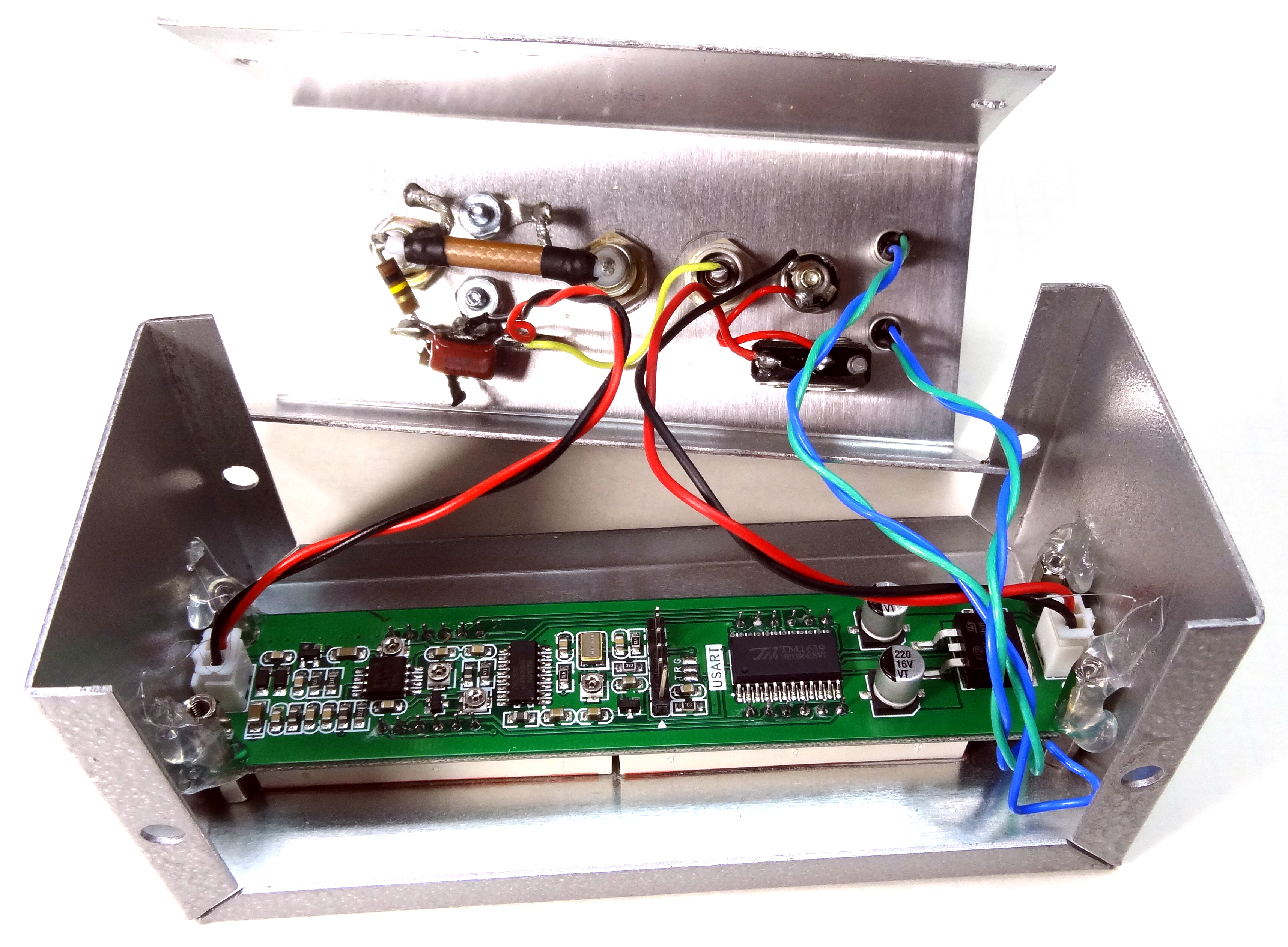 Photo showing the two mini-box sections and the interconnecting wiring. The thru coax connections and RF sampler on the left with coax connector for whip antenna at center, the 12V input, power switch, and the two push programming switches on the right
 Closeup view of the display board showing the four corner hot glue mounting.
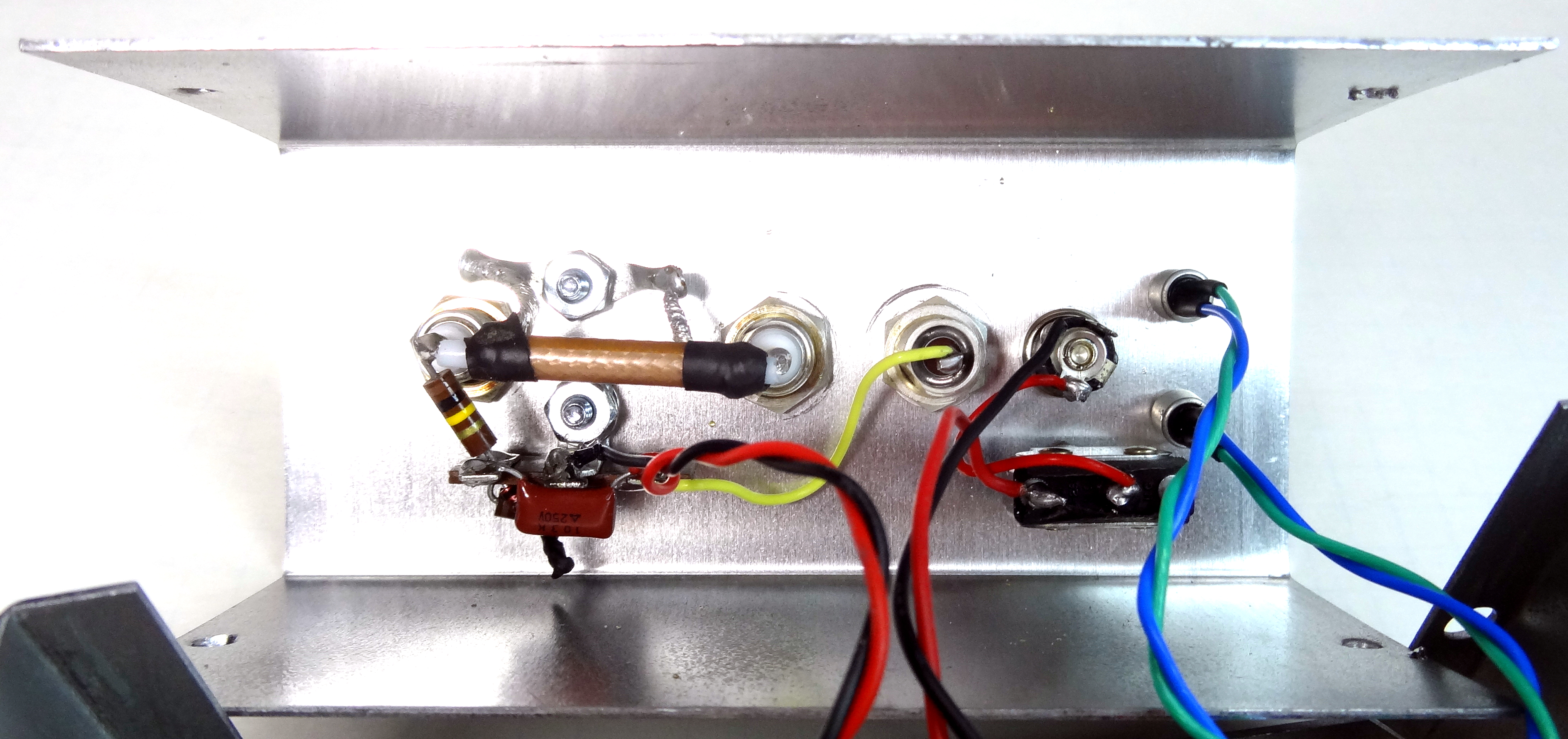 Closeup view of the inside back panel showing the RF sample parts on the right and the 12V input and program switches on the left.
 Unit ready to assemble
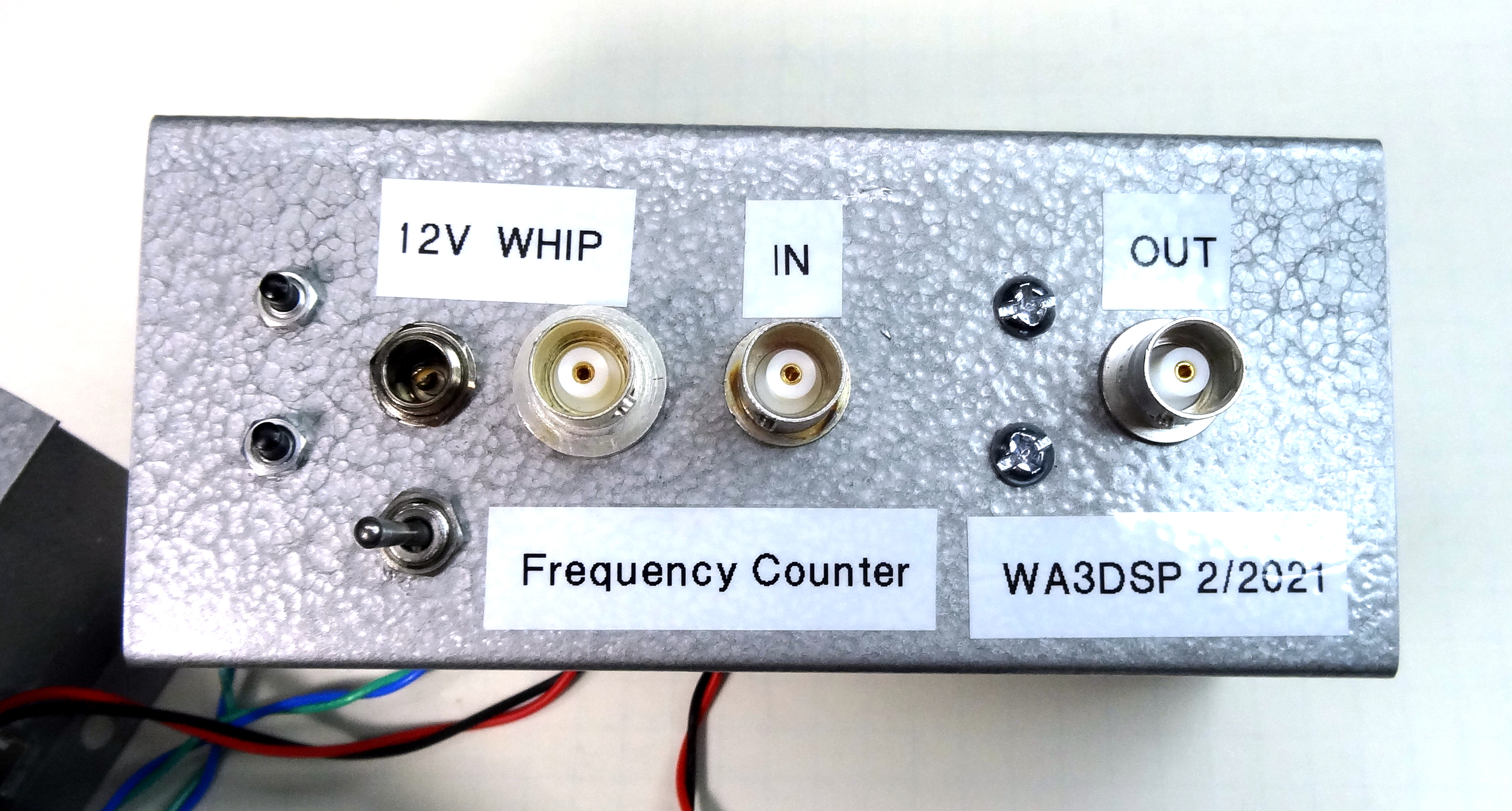 Rear panel, Programming switches, power switch and 12V input, whip antenna input, thru antenna input.
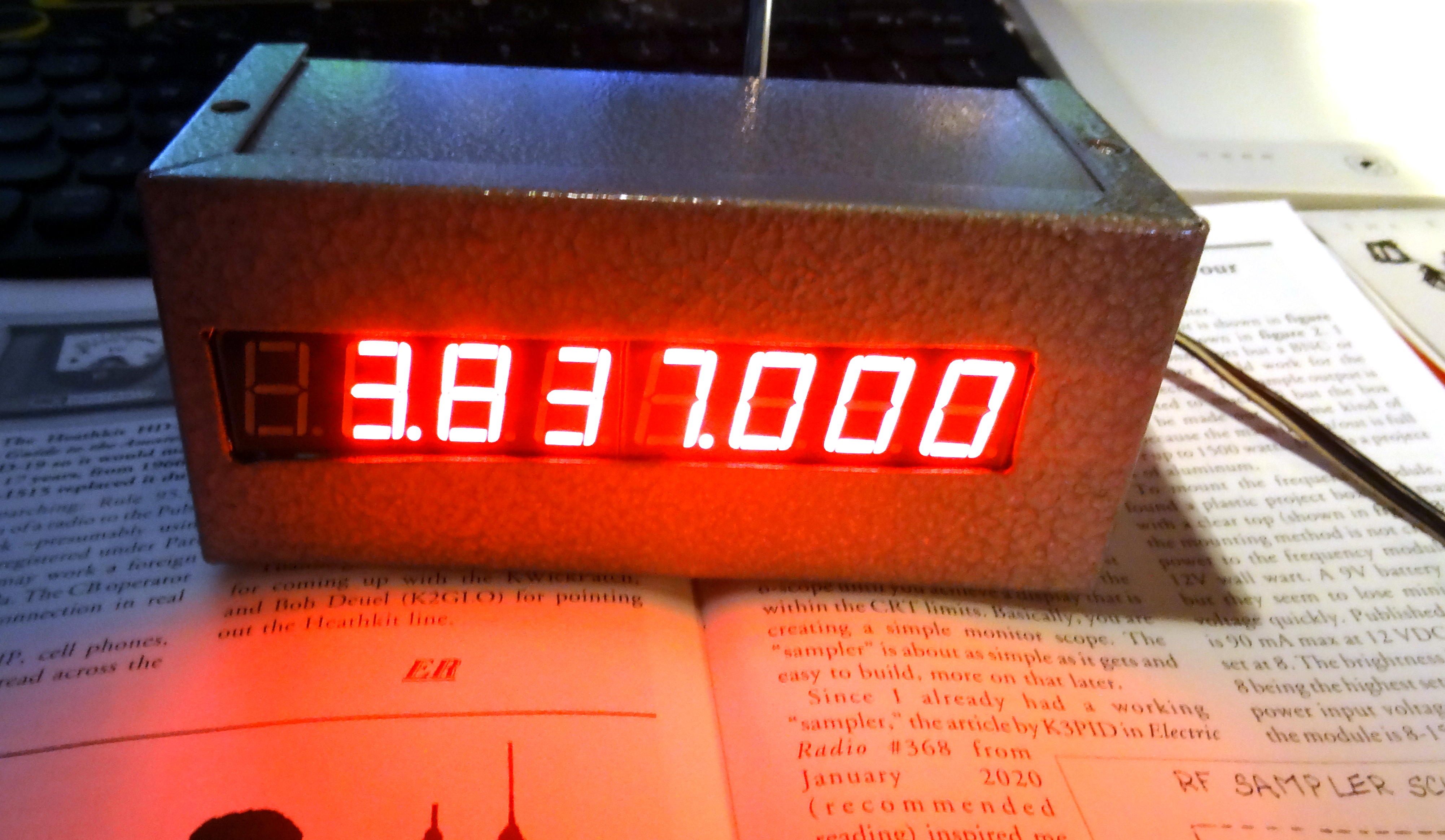 And finally a photo showing a display of our AWA 75 meter channel 3837 transmitted from my Kenwood TS-590 on an 80 meter dipole and picked up by the whip antenna on the counter.
Compare this to the Vintage 1960's Hewlett Packard nixie tube counter which weighed close to one hundred pounds and had a ton of tubes!
This page last updated 2/26/2021
© 2021 - WA3DSP