Harvey Wells Bandmaster
TBS-50C Modified to 50D and Restoration
Harvey Wells History
Harvey Radio Laboratories
12 Boylston St., Brookline, MA
Harvey-Wells
Southbridge, MA (1940)
Founded:1933 Closed:1968 Production started:1933
In 1940 Clifford A. Harvey (W1RF) and John Wells (W1ZD) joined and started the Harvey-Wells Electronics company in Southbridge, MA. The company was previously known as Harvey Radio Labs. Harvey-Wells produced 85% for military purposes and they where awarded the Navy “E” award for excellence during WW II. The famous Harvey-Wells TBS-50 first appeared in QST of 1948. In 1957, the company has been acquired by "Within Machine Works", the "Harvey Radio Labs" company still existed and became owner of broadcasting stations.
My Bandmaster TBS-50C Restoration Project
(Click any photo to see a larger view)
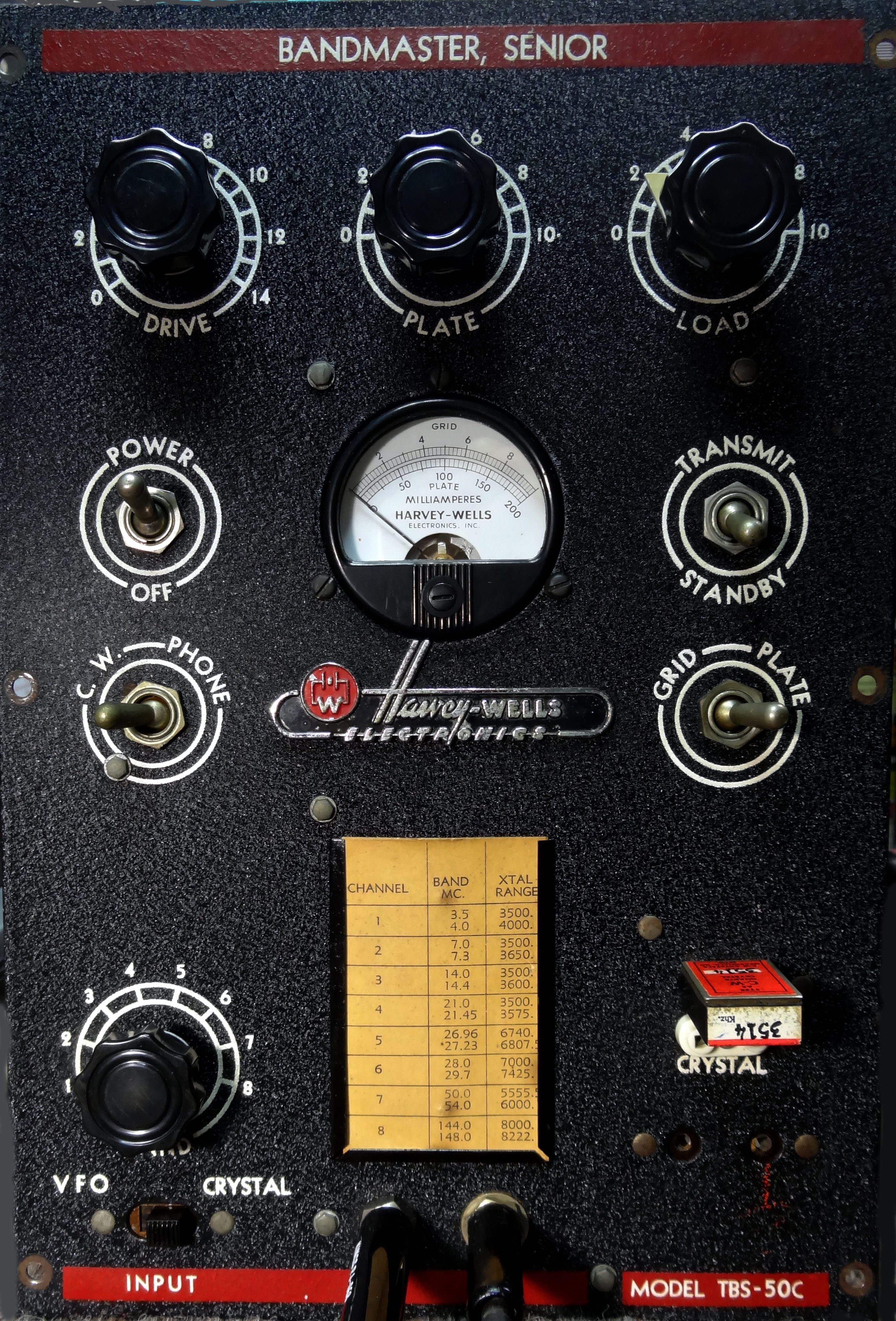
I don't recall where my TBS-50C came from. It was given to me from some estate many years ago. It set on the shelf for years before I finally decided to restore it in early 2020. My first project was to build a power supply for it as documented here. The Bandmaster had a very good front panel. The only change was the addition of an HC6 crystal holder by a previous owner. Internally it had seen some wear but after a cleaning and removal of some previous mods it was ready for my restoration.
Power Supply
The home-brew power supply I built was designed around the original Bandmaster AC supply but differs in several ways. I do not switch B+ in the supply. It is always sent to the transmitter which is modified to have a combination antenna and B+ relay keyed by the transmit/stand-by switch or PTT from the mic. The supply is choke input and provides around 400V B+ at 200ma. This is slightly less than the recommended maximum voltage but it was the best combination transformer I had and with old wiring I thought it would be better to keep the voltage on the lower side. This lowers the transmit output power slightly. There is no difference at the receive end between 18 watts and 25 watts so don't sweat that! The supply uses an 8 pin female octal socket wired like the original except for the PTT pin which instead is 17V DC output to the transmitter to power the relay and also the class D audio amplifier described later. This low voltage DC is derived from a series connection of the 6.3VAC and unused 5VAC windings rectified and filtered.
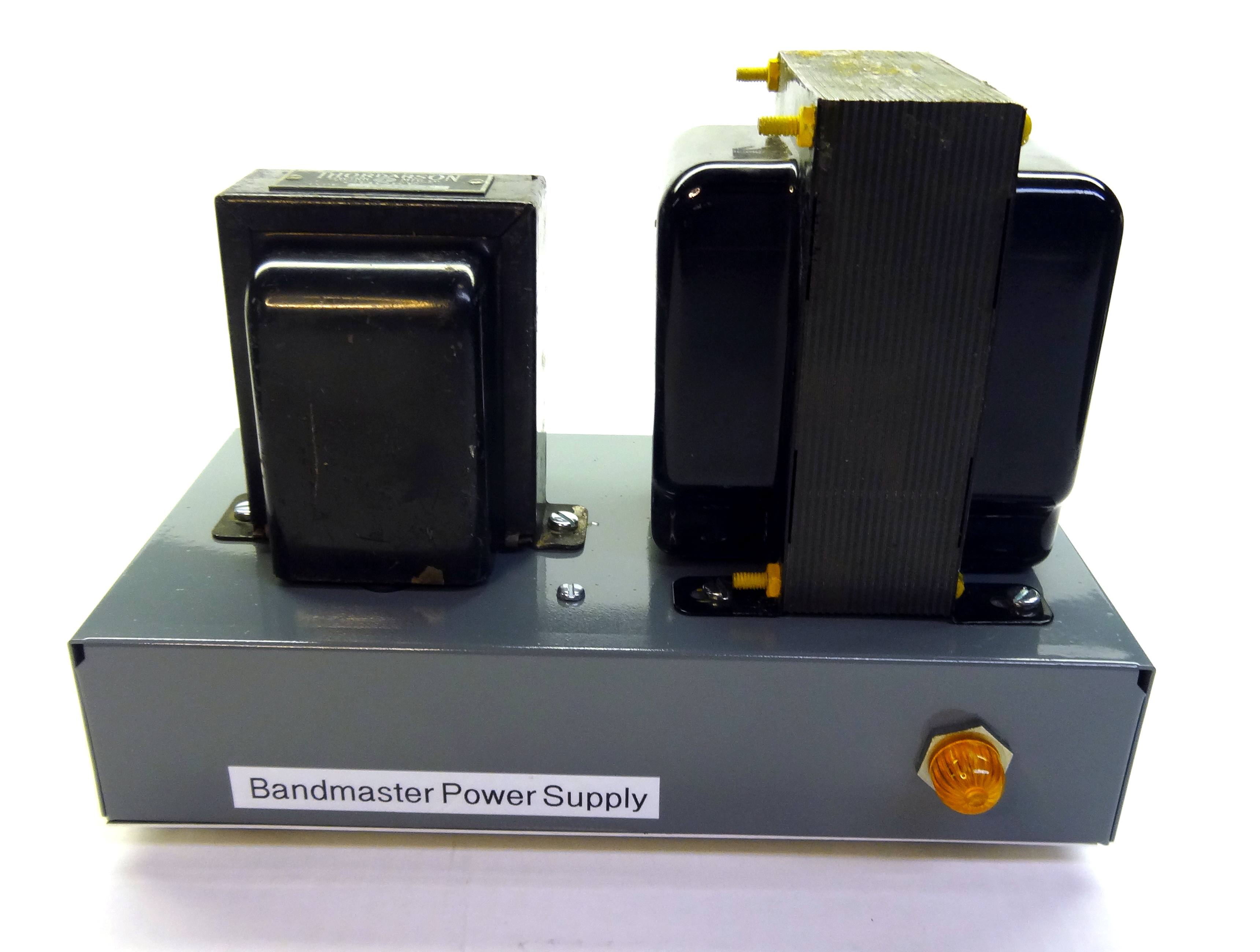 Front side of the power supply. Pilot lamp is an LED bayonet replacement for #47 bulb.
 Back side of the power supply. The power switch is part of the EMI filter/fuse assembly. No AC switching was sent to the Bandmaster. AC power is controlled by the power supply switch. The power switch on the transmitter was modified to become a tune operate switch.
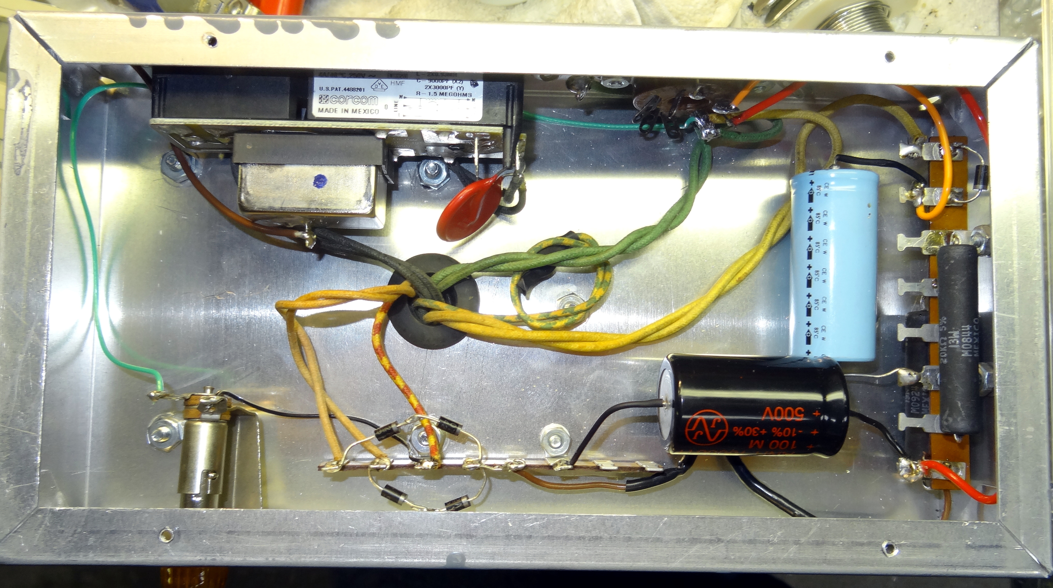 Underside of the power supply. The supply is choke input with 100uf of filtering. The other large capacitor is filtering for the 12V supply.
TBS-50C Restoration/Modification
Whenever I look at a restoration project I always have in mind improvements to the original design. Looking at things that were designed 70+ years ago you often think "why did they ever do that!" or "there is a much better way to do that." In the case of the bandmasters there are several things that fit those thoughts. I would never touch the front panel but otherwise the design is always up for improvement.
This was a TBS-50C which is the carbon microphone version. I even have several of the original carbon microphones used with the TBS50. The transmitter however was missing the microphone input transformer and while I could have replaced it my thought was that no one would like to hear a carbon microphone on the air today. So I added a class D amplifier and a backwards push-pull audio output transformer to drive the 6L6's which were actually replaced with 5881's. An aluminum panel was formed to hold the small class D amplifier and the modulation pot which lines up nicely with the original hole on the right side of the case.
An antenna relay was added which also switch B+. This relay is keyed by the transmit/stand-by switch in CW mode and either the transmit/stand-by switch or the PTT in Phone mode. Two BNC connectors were added to the back panel for antenna and receiver connections. Several components were replaced and/or moved to more appropriate locations. B+ was removed from the final tank circuit and a wafer was added to the band switch to add needed capacity on 80 and 40 meters.
 A previous owner had added some kind of antenna output filtering which was removed
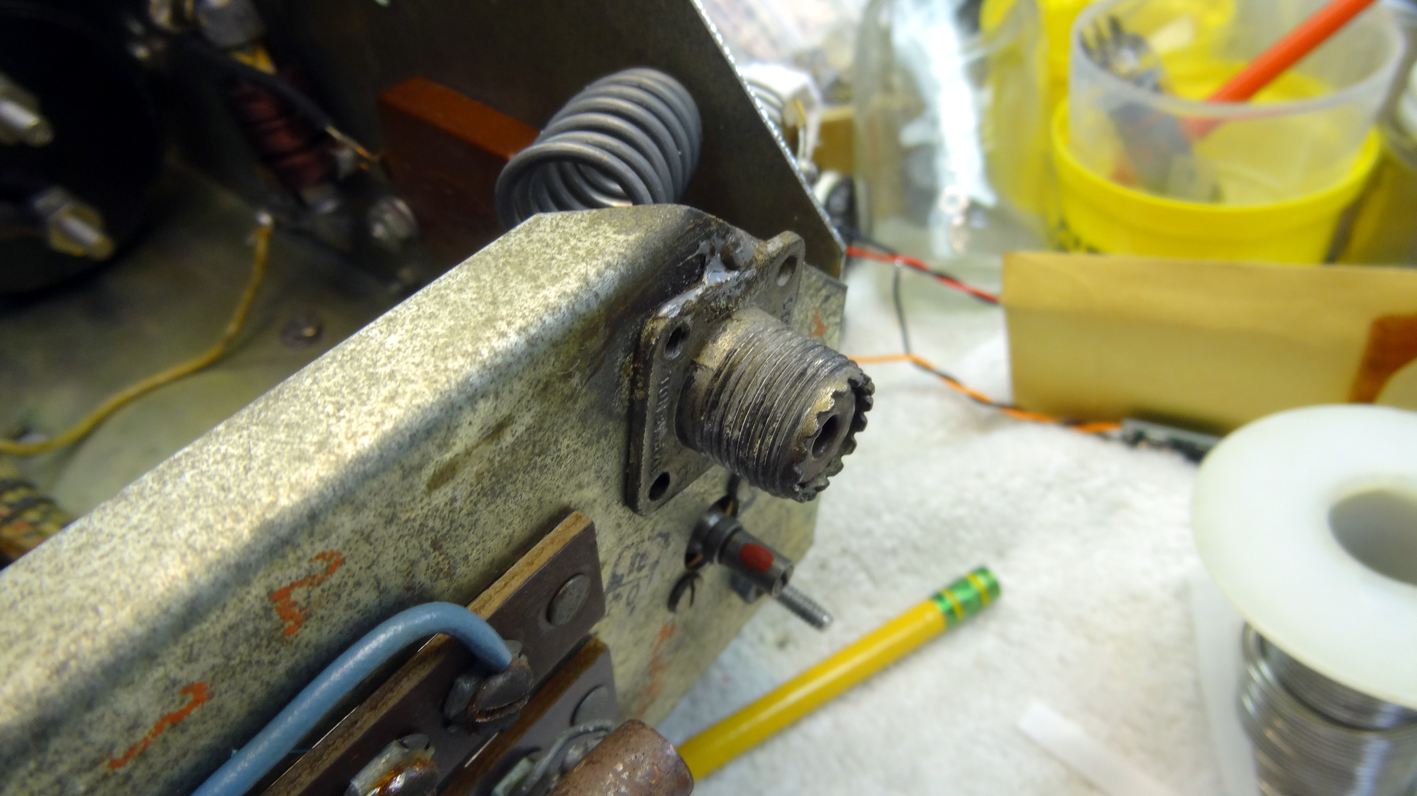 and also removed was a rear panel SO239 antenna connector.
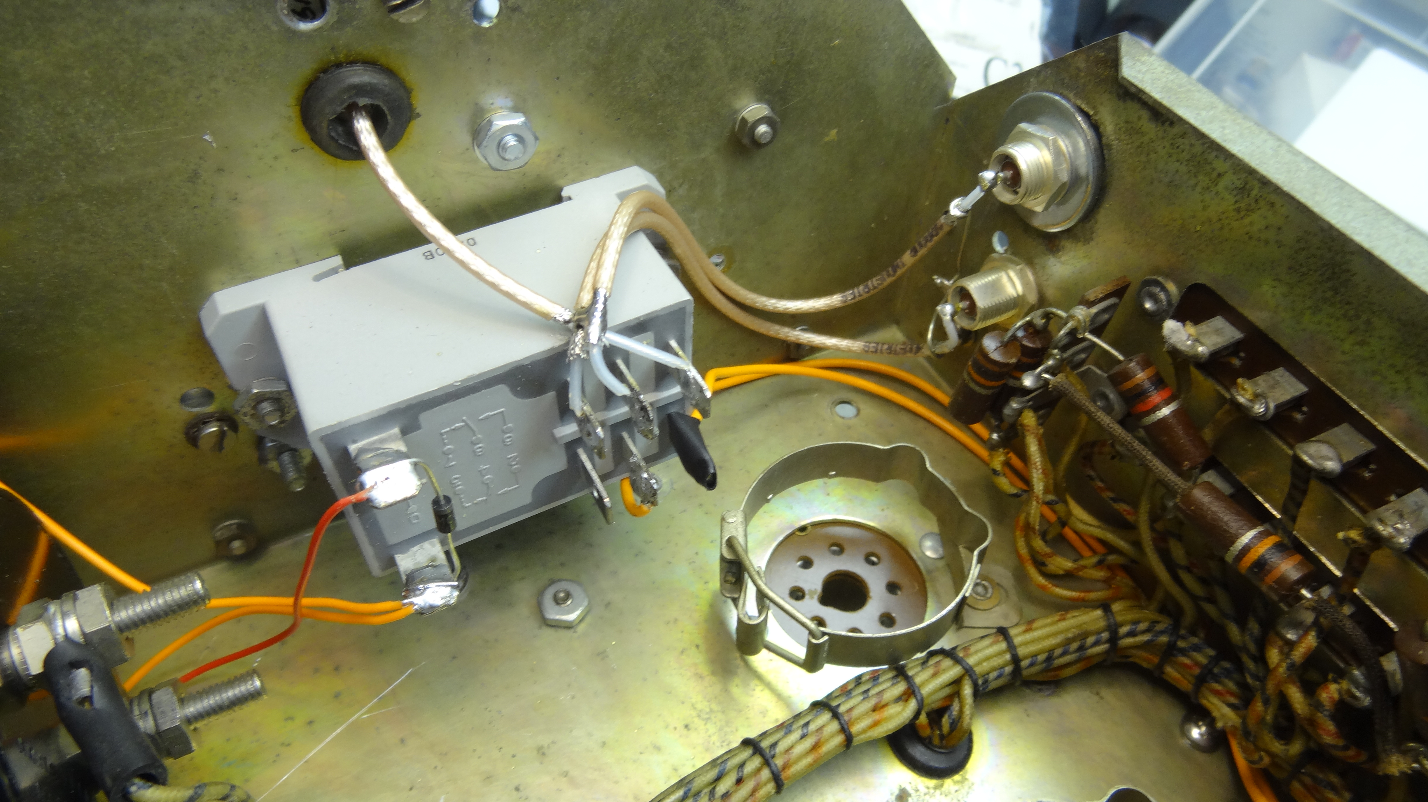 This was all replaced with an antenna relay and two BNC connectors on the rear panel.
 Rear panel Antenna and Receiver BNC connections.
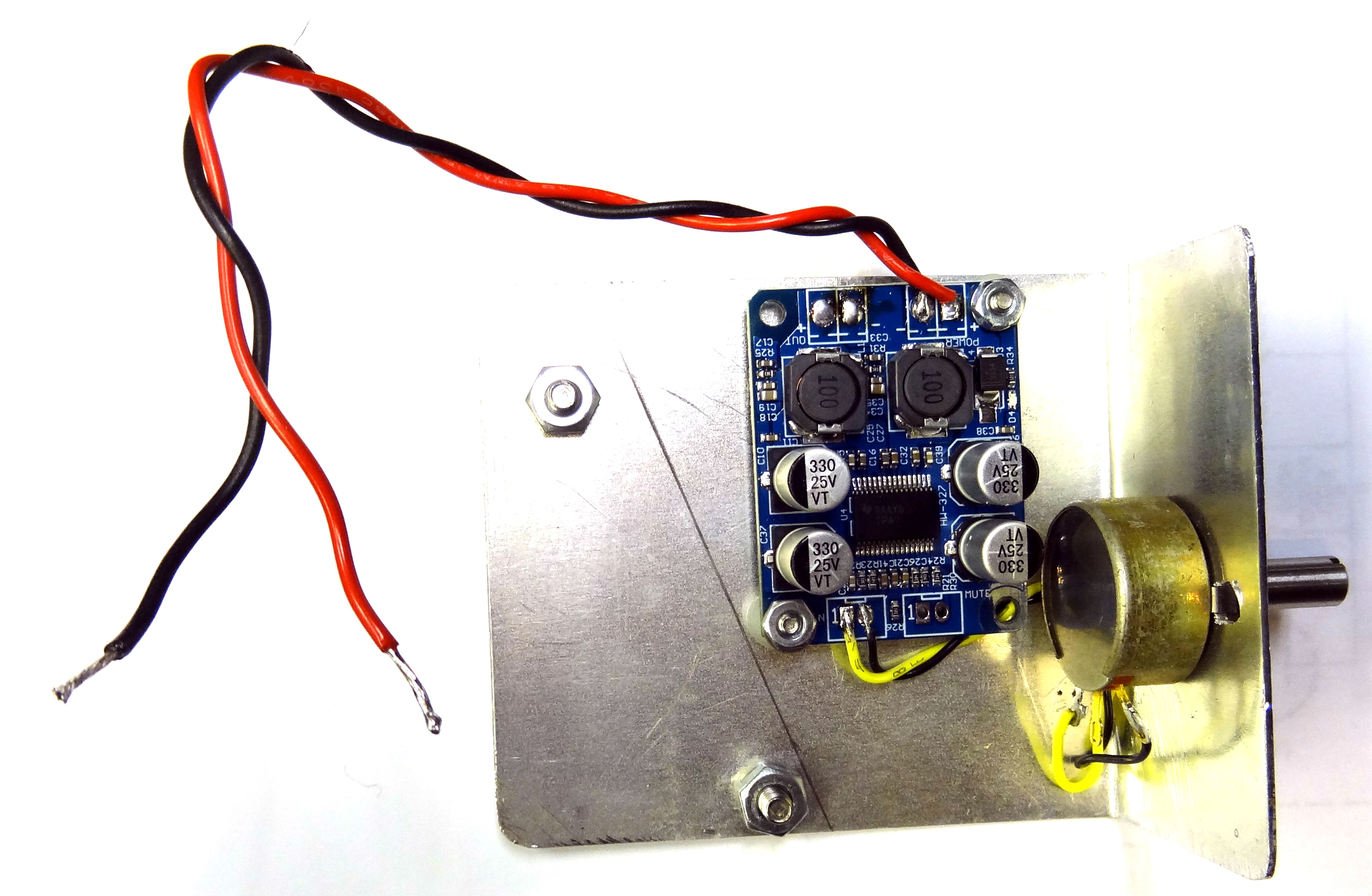 The class D amplifier mounted on aluminum plate with pot.
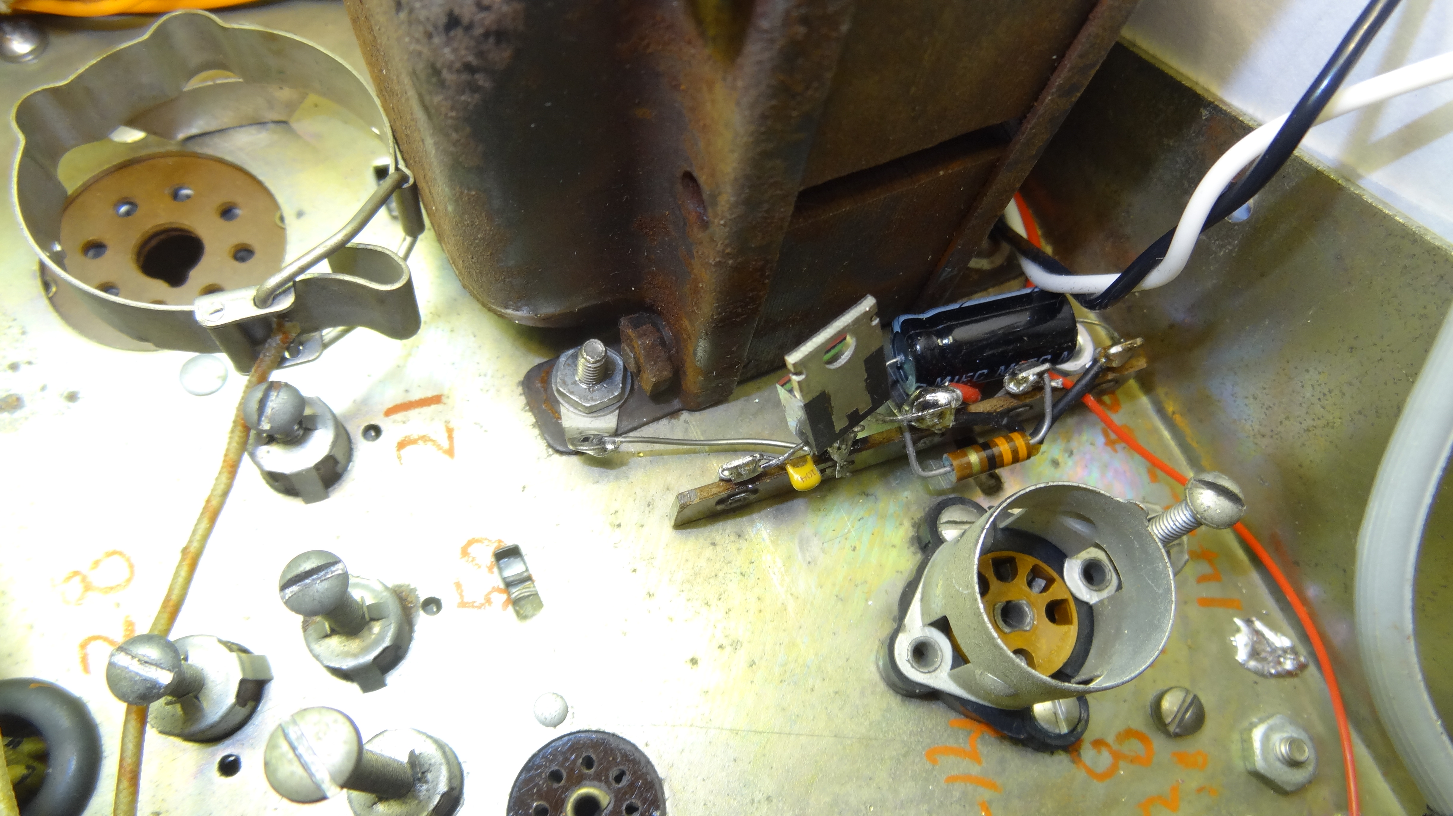 Electronics for Class D amplifier - 12V regulator
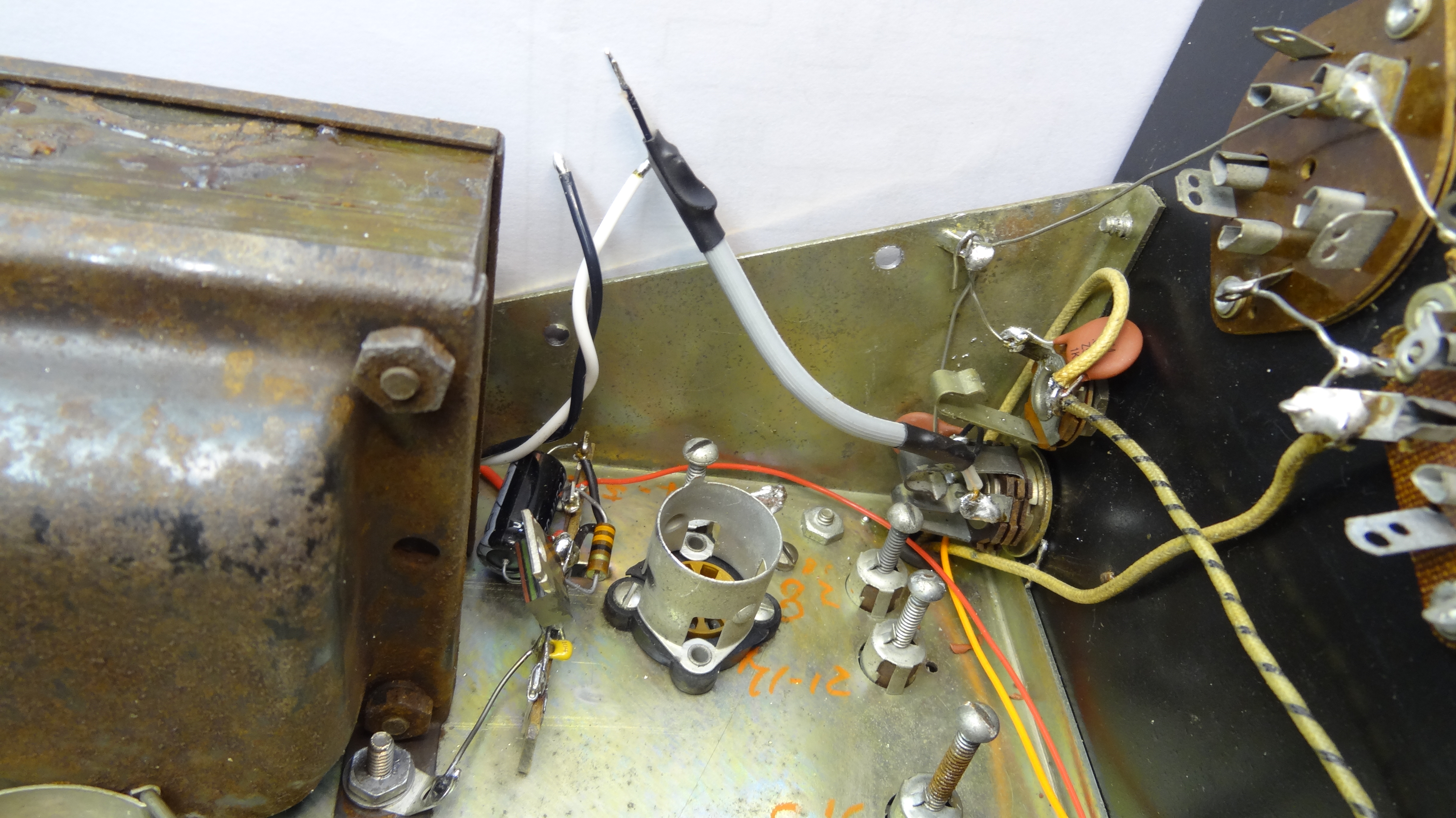 Wiring ready for the class D amplfier.
 Mounted class D amplifier assembly.
 Another view of mounted class D amplifier assembly. The pot adjusts the modulation level and is accessible through a factory hole on right side of the cabinet.
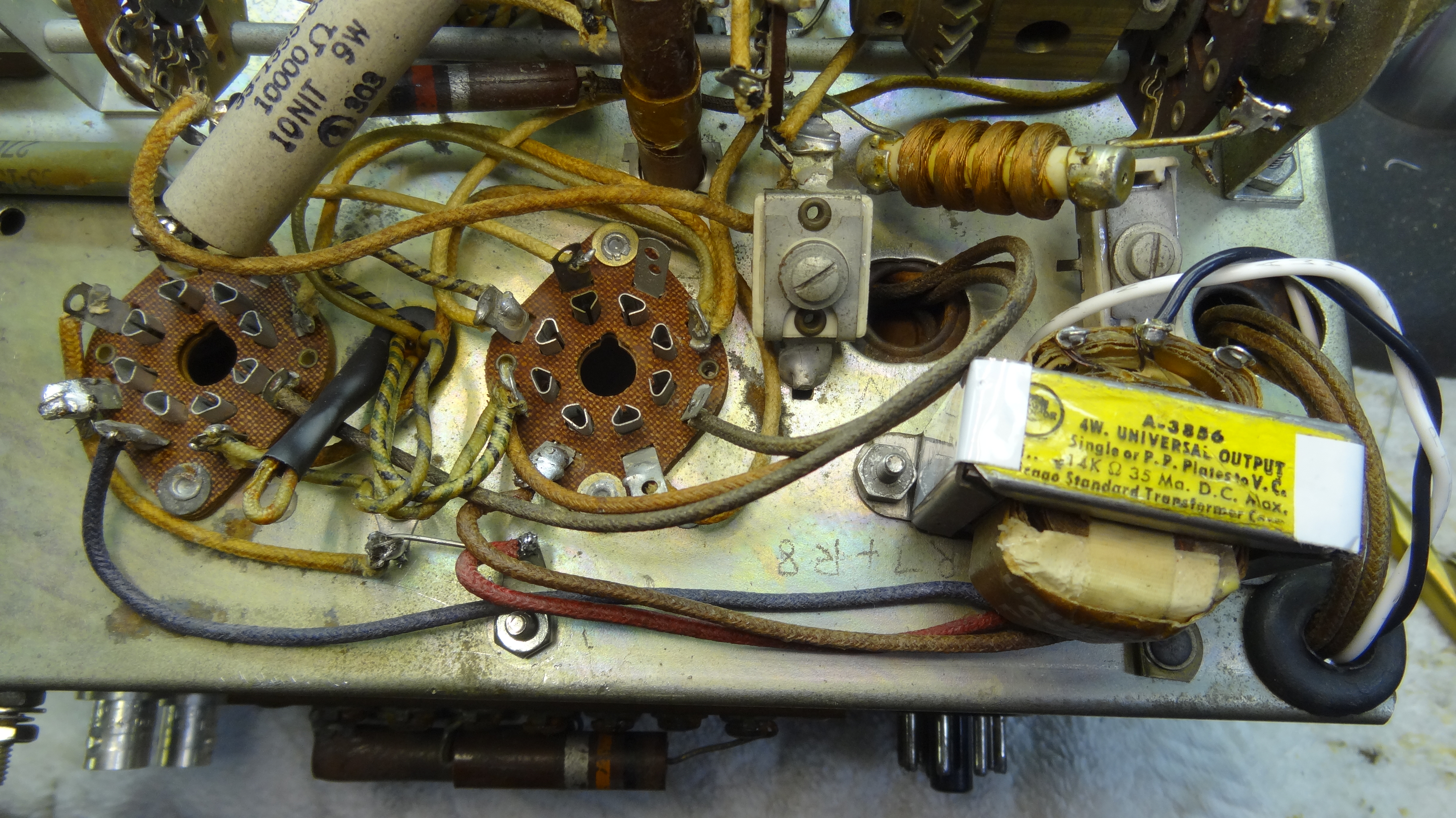 View showing Class D amplifier to push-pull grid transformer. Not shown in this view is that pin 1 of both 6L6 sockets were grounded. This is a no connect on glass 6L6's but is the shield if a metal 6L6's were to be used.
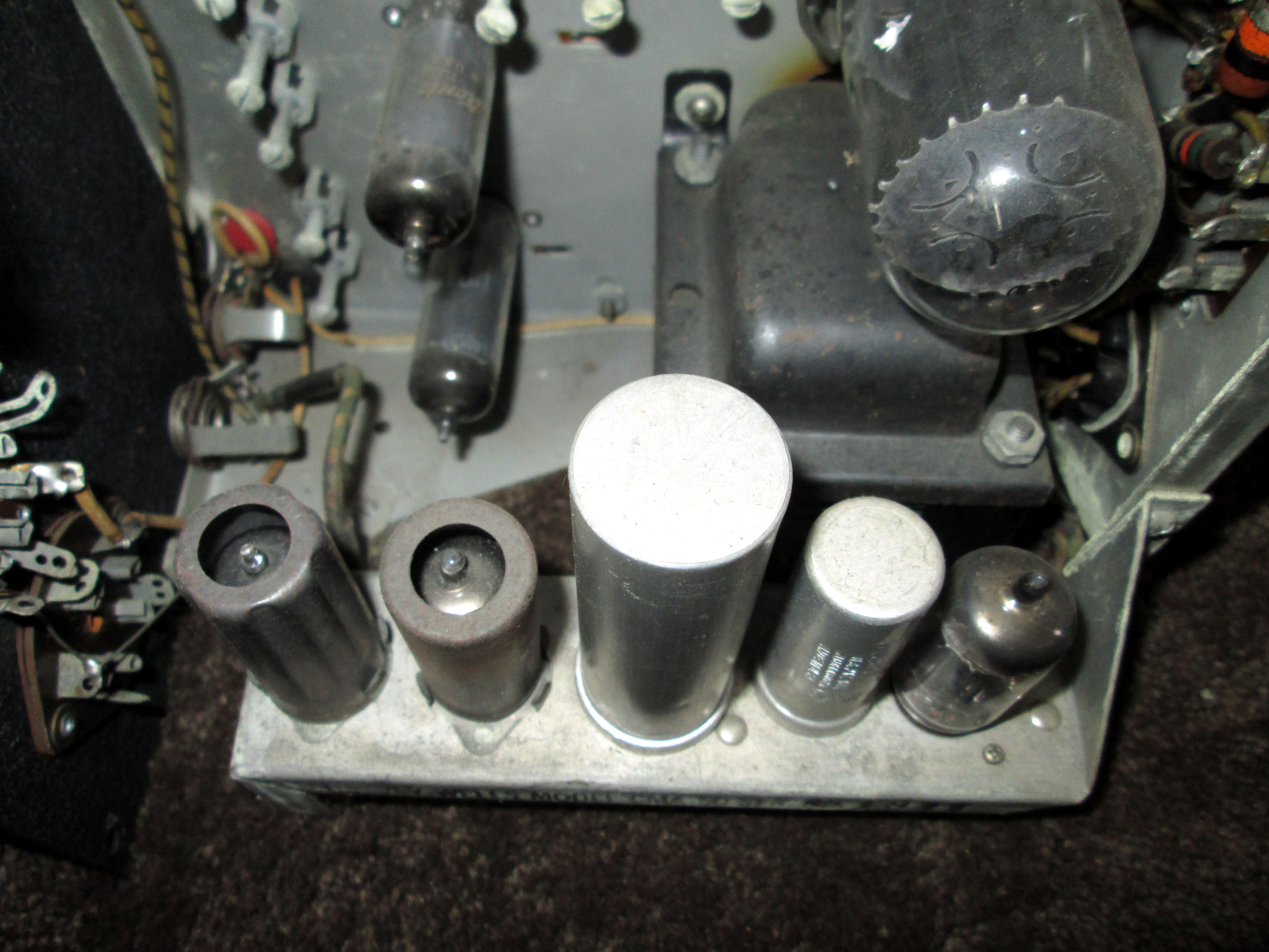 Comparison view of what the model D vacuum tube add-on deck would look like.
 Another view of what the stock model D audio deck would look like compared to the solid-state class D board used in this mod.
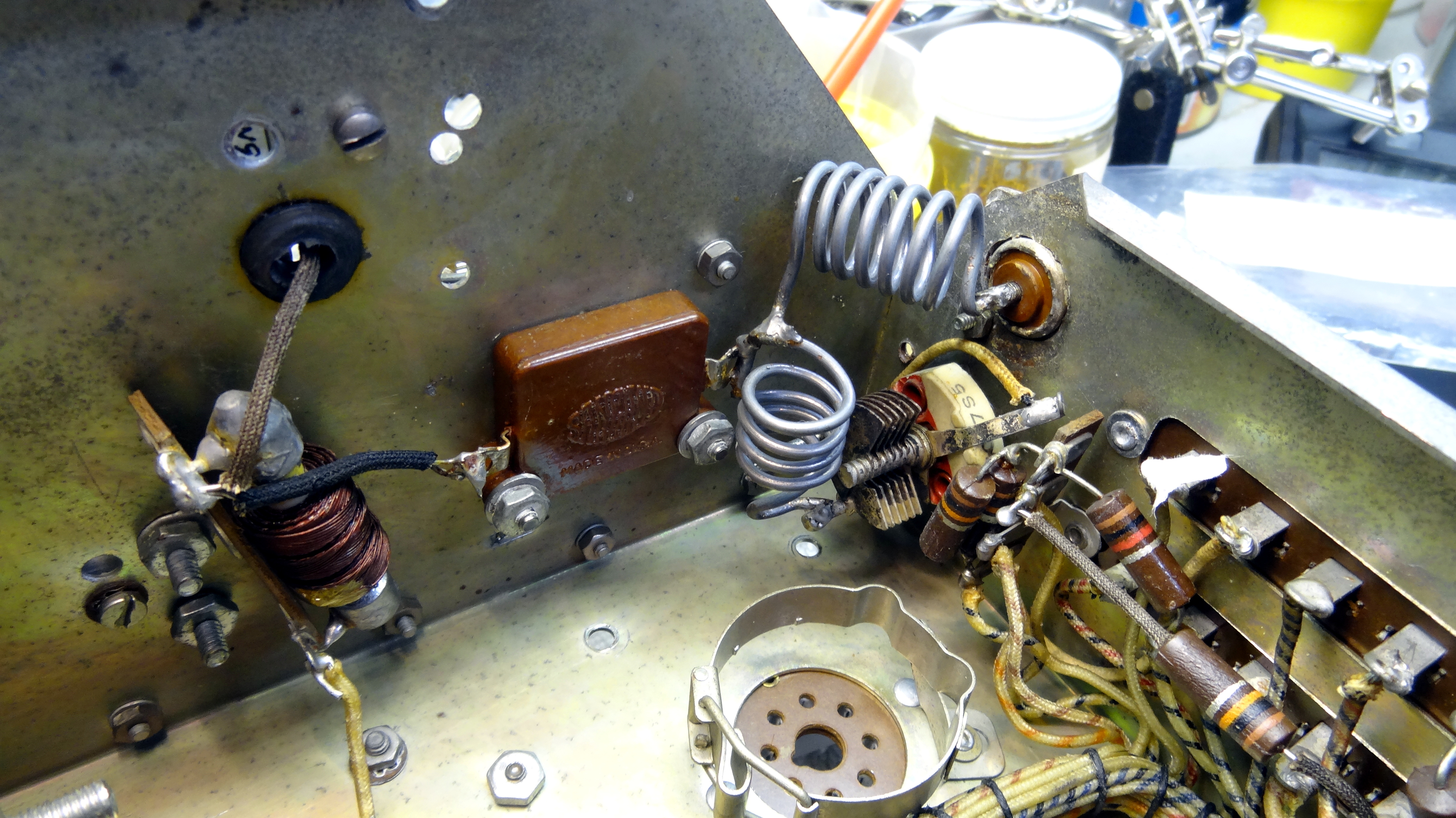
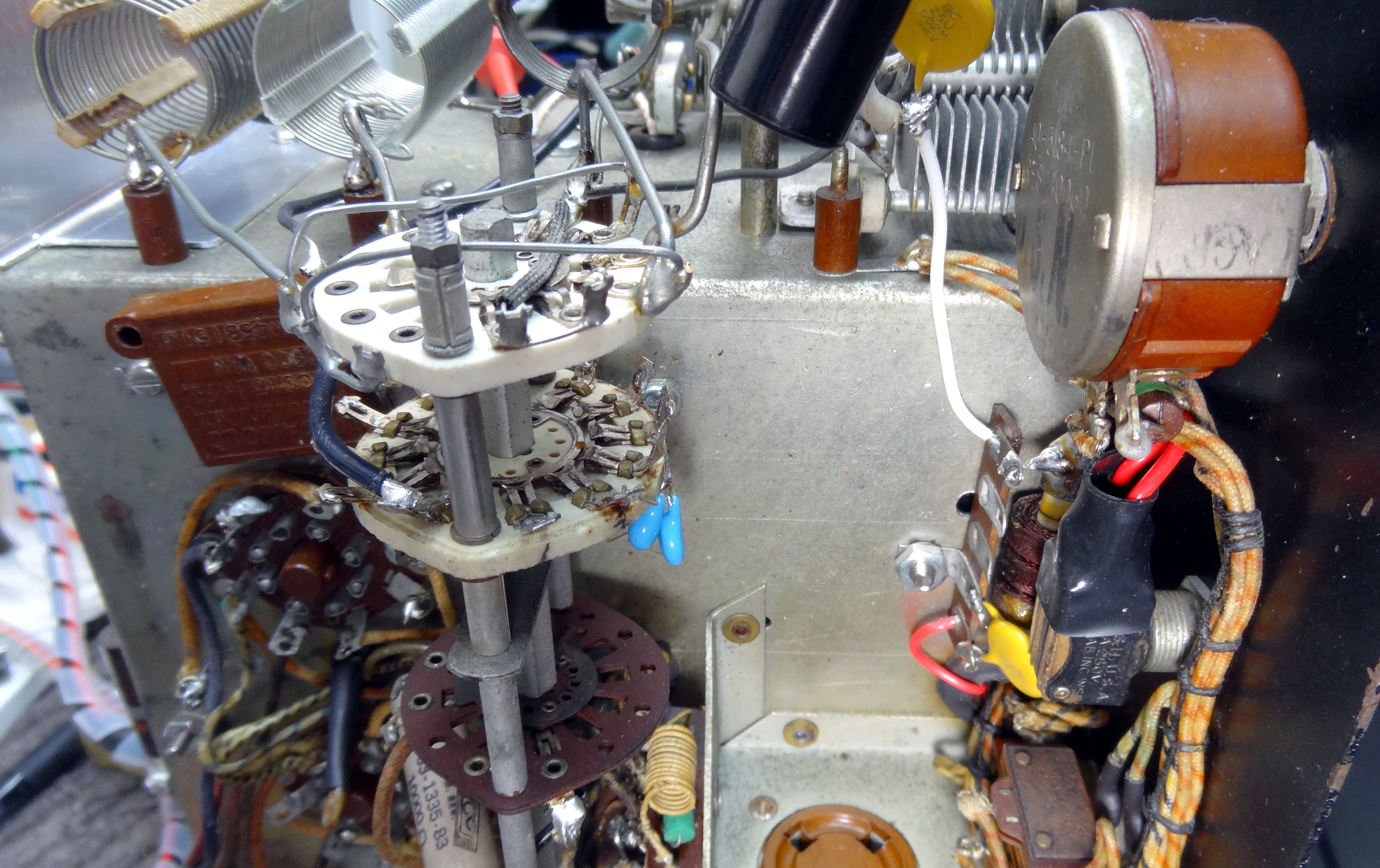 View showing added ceramic wafer just below final bandswitch wafer for adding loading capacitance.
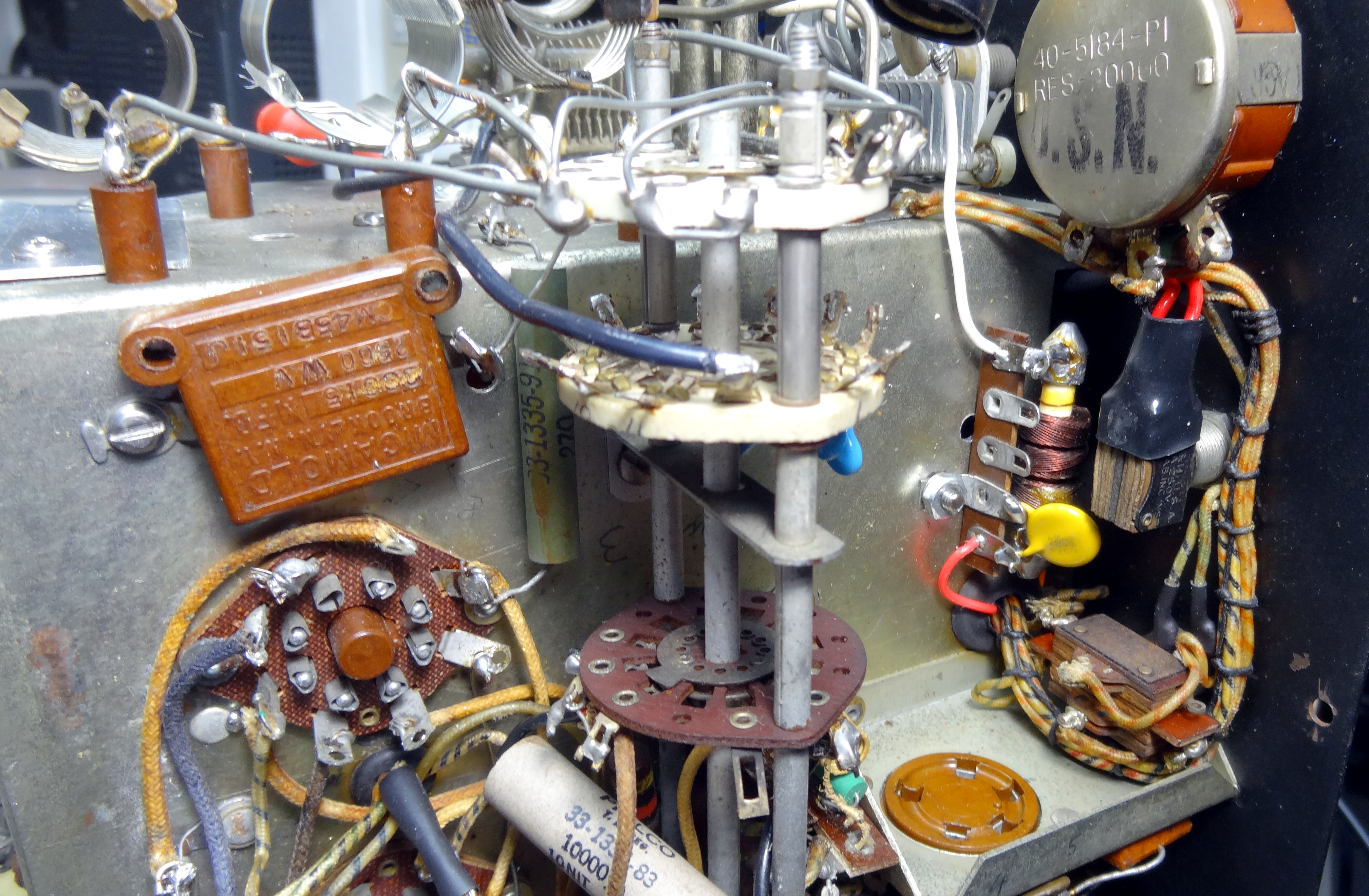 Another view of added wafer. Note the modification of the power switch to the right. Instead of power it has become a tune/operate switch lowering final screen voltage in the tune position. This photo also shows the relocation of the mica loading capacitor and the final RF choke and modification to remove B+ from the final Pi components.
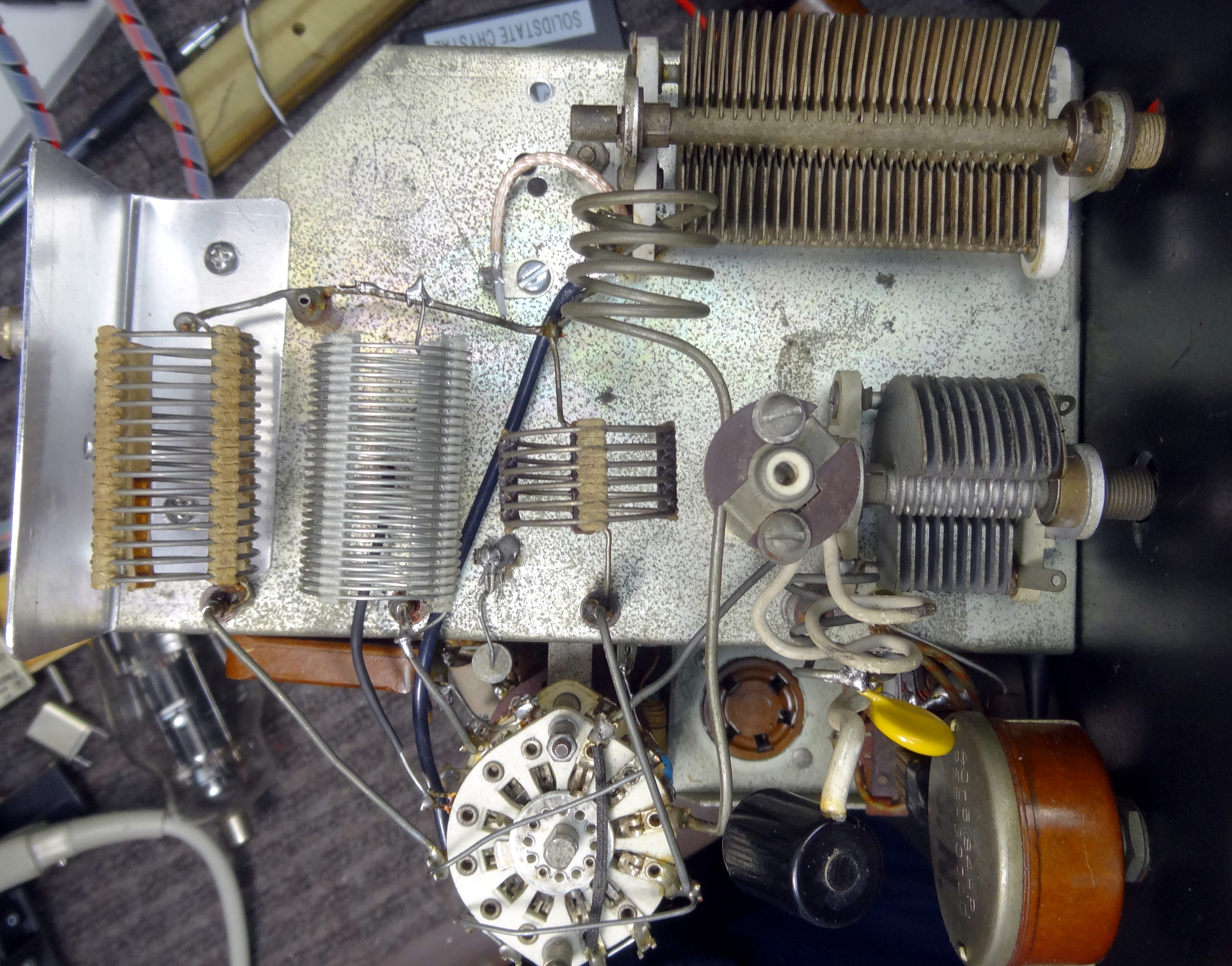 Pi output circuitry showing new 80/40 meter coil installed. Added yellow disc ceramic plate blocking capacitor is shown near 807 plate cap.
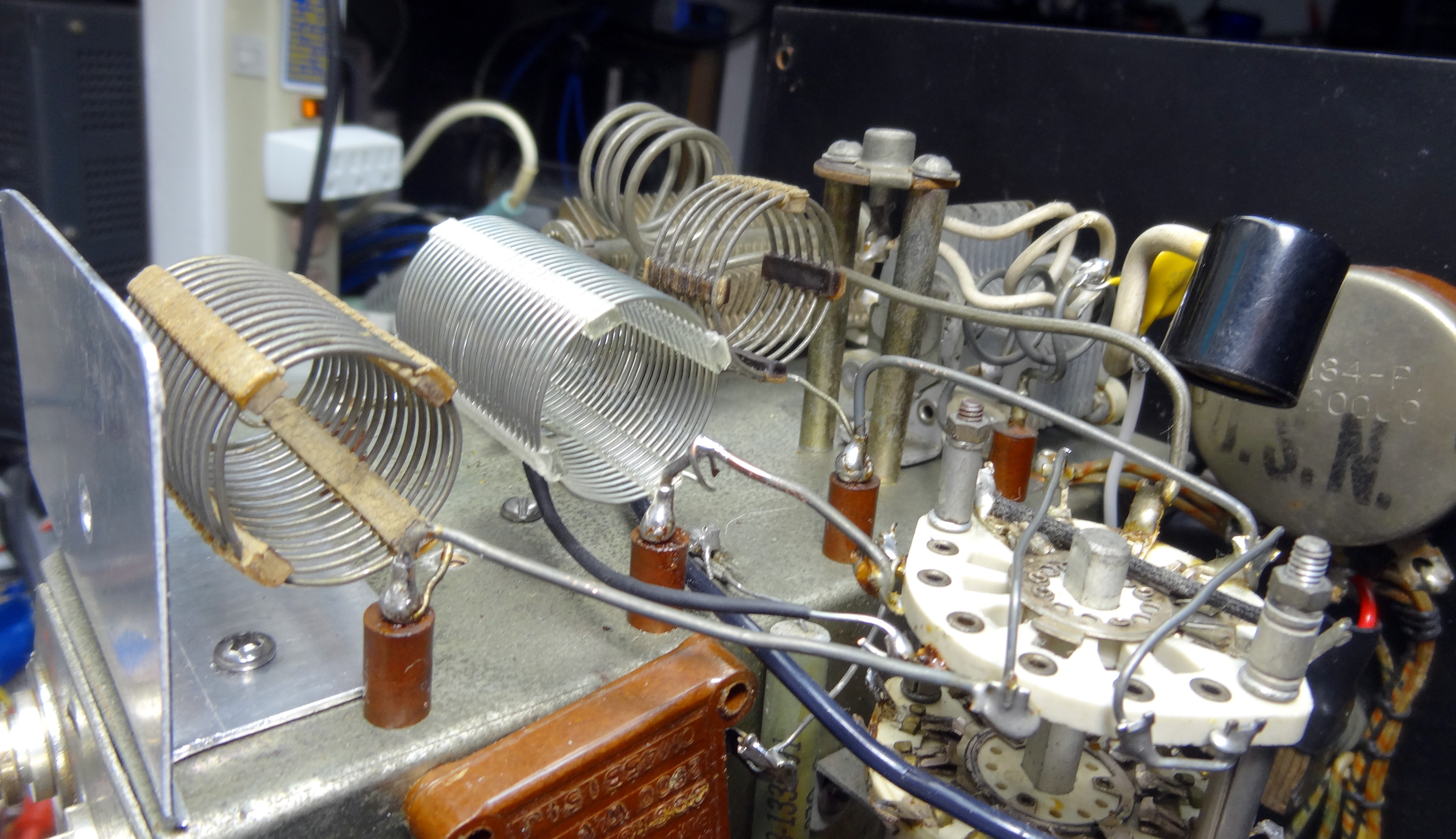 Side view of the final Pi circuitry. An aluminum shield was fashioned at the rear to protect the coils when working on the transmitter.
Additional references
Harvey Wells Radio Links
- John M. Wells, W1ZD, The Wizard of Southbridge!
- Listing of all Harvey Wells products
- Cliff Harvey recalls
- R9A Restoration
- Models produced
- QST Old Radio Article
- TBS50 eHam review
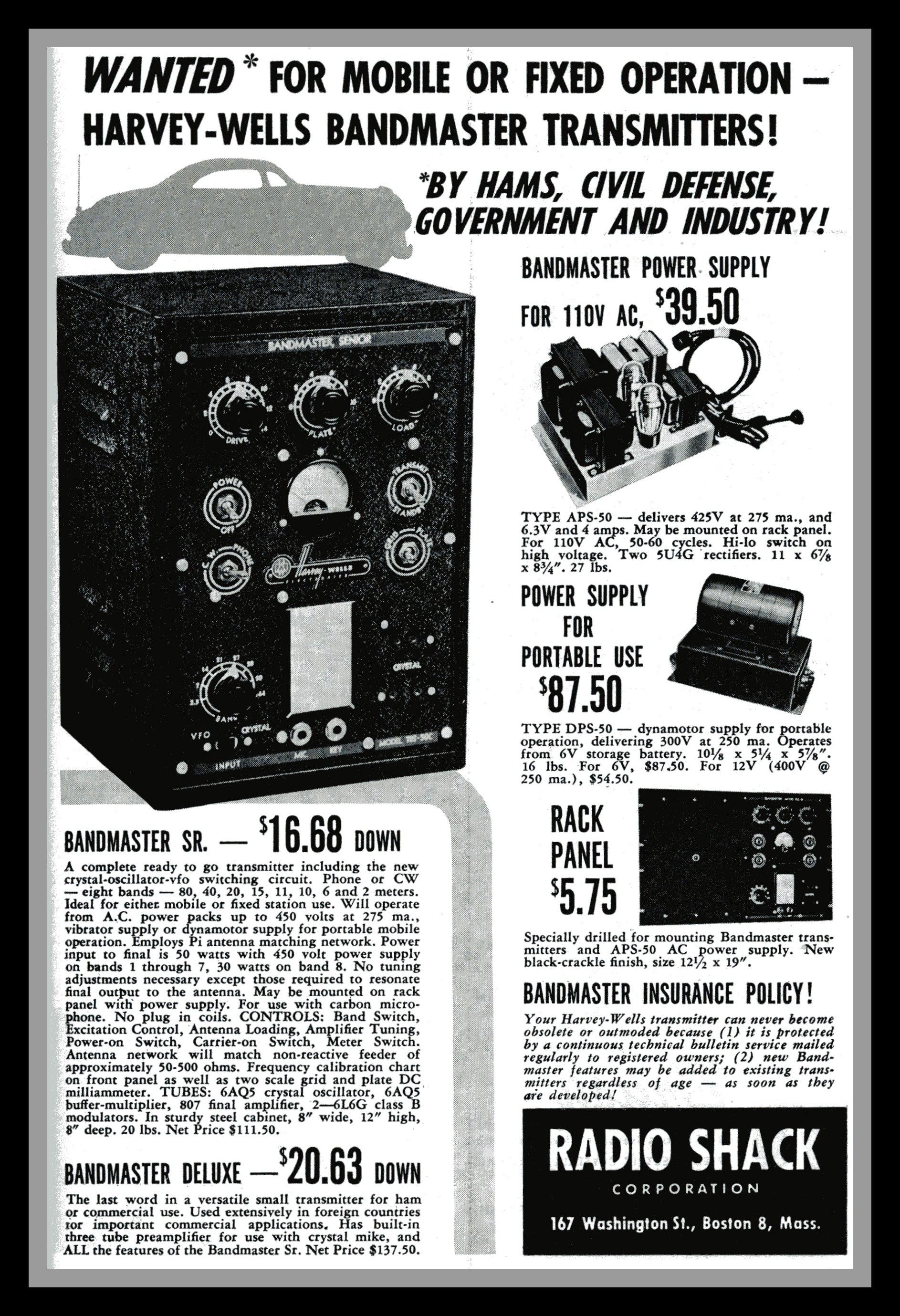
- Original Advertisment for Bandmaster and accessories
- Interesting article showing Philadelphia area ham with TBS50C mobile
- Interesting old radio museum
- WA4FTY, The Harvey Wells Guru
This page last updated 5/22/2020
© 2020 - WA3DSP