E.F. Johnson Ranger Transmitter Restoration
Johnson Radio History
There is little detail on the web about the history of Johnson Radio. The following paragraph was taken from Wikipedia which in turn references the current E.F Johnson Technologies Company that makes commercial communications equipment. They no longer have any Johnson history at their site. It is a sad ending for a company that meant so much to Amateur Radio.
"The company began as a mail order business, selling radio transmitting parts to amateurs and early radio broadcasters and was active in World War II defense production. After the war, the company introduced its Viking line of amateur transmitters, among them, the Viking, Valiant, Ranger and Pacemaker. The company transitioned to development and manufacturing of land-mobile radio products such as CB, business radio and associated technology such as the Logic Trunked Radio trunking format. EFJohnson's discontinued Viking line of amateur radio transmitter products are collected, restored, and operated by a number of vintage amateur radio enthusiasts."
Johnson Ranger History
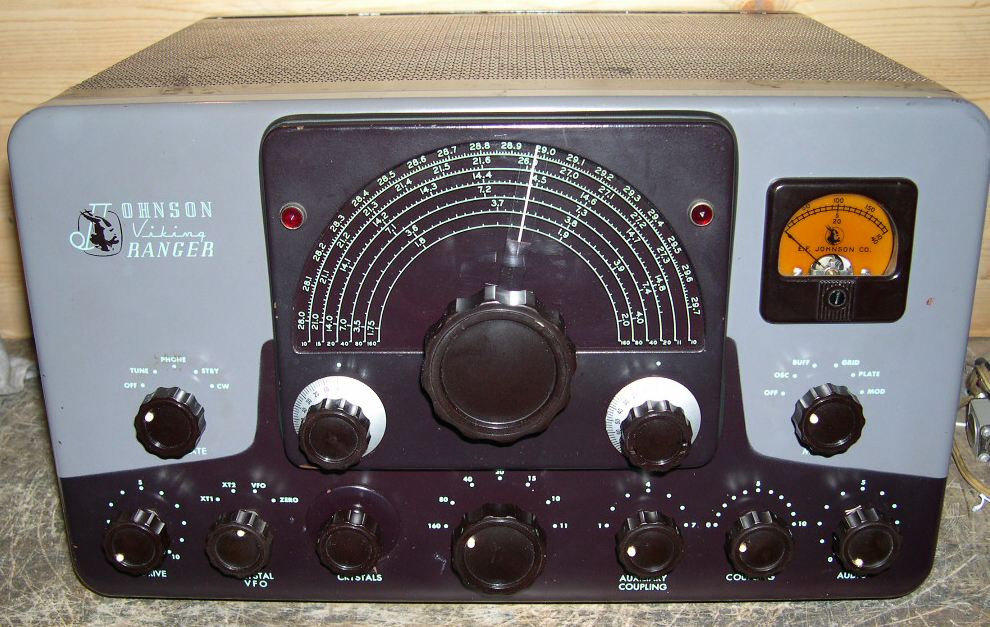
The Johnson Ranger was first introduced in 1954 both in Kit and wired versions. The original kit sold for $179.50 and the wired version was $250. It had the classic maroon and gray Johnson colors. It was a 65 Watt input AM / 75 watt input CW Rig. The final tube was a 6146 modulated with push pull 1614's. It had a built-in VFO and Power Supply and weighed 45 lbs. The first versions had cathode keying and used cathode bias on the push-pull modulator.
A later update added a power transformer that had bias taps, a keyer circuit to improve CW operation, and fixed negative bias to the modulator.
The Ranger was manufactured until 1961 when the Ranger II was introduced. This had a new color scheme and changed the push pull modulator tubes to 7027A's. It was manufactured until 1965.
My Johnson Ranger Project
(Click any photo to see a larger view)
Usually when winter comes around I look for inside radio projects. This year it started off with a Johnson Ranger. It had been given to me many years ago by a local ham and has set on one of my museum shelves even since. He told me that he purchased it used from one of the ham radio retailers in the early 1960's and used it for many years in his early ham career. I recently remodeled my upstairs shack and I was looking for a good and not too heavy AM rig to use there and the Ranger seemed a perfect candidate. So I pulled it off the shelf and entered into an aggressive to month restoration project.
On the outside I classified it as fair to good condition. There were paint chips here and there but no obvious mods like holes in the front panel. Inside was a different story. It had been a kit manufactured around the 1955-57 period. Construction was rather good in some places and not so much in others. It was almost like two different people built it. The only mods were the factory designated B+ PTT relay and the replacement of the HV rectifier with a solid-state plug-in. It was extremely dirty inside, a combination of grease and probably nicotine typical of rigs from that time. All other parts looked original.
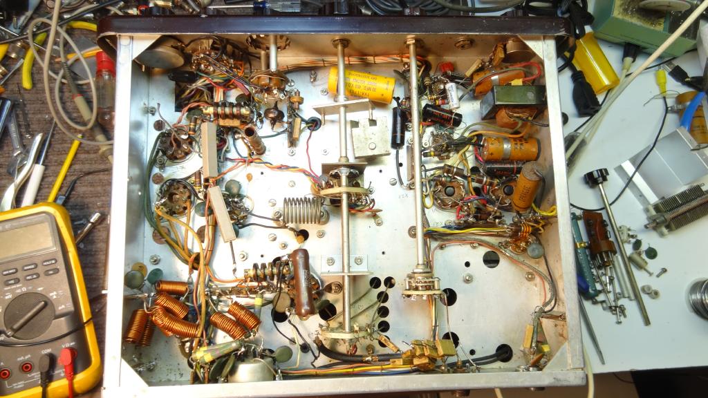 This was the first photo I took of the Ranger in this project. I had already ripped quite a few components out.
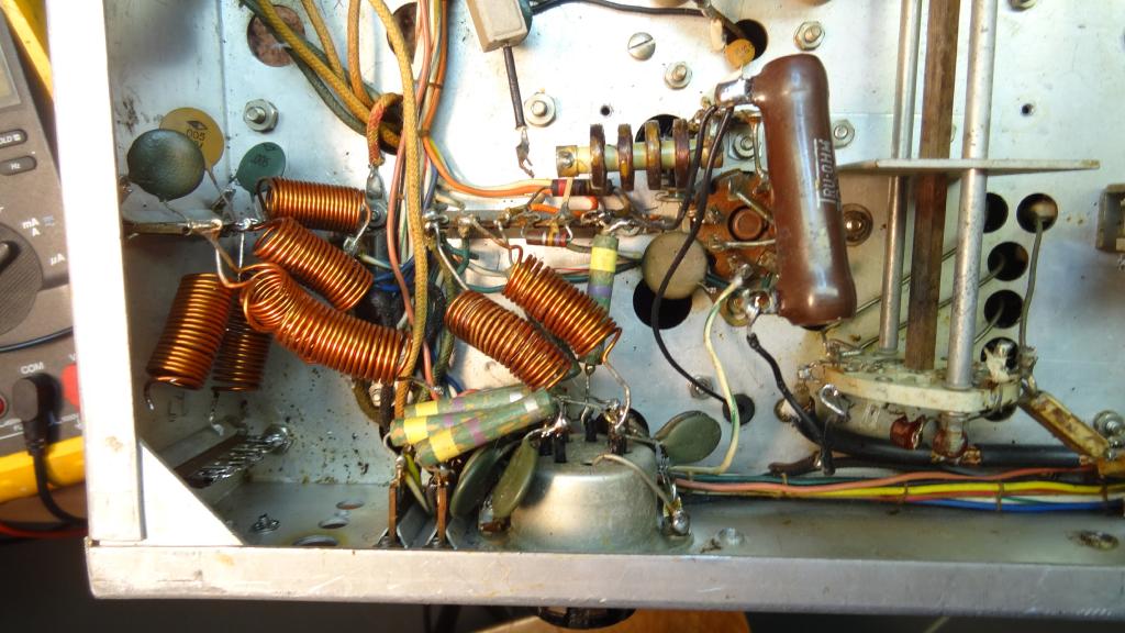 The mess in the right rear of the under chassis. The Johnson TVI filters and large screen resistor still there.
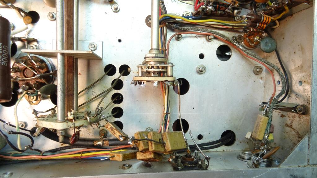 Under chassis left rear, Fixed loading capacitors unsoldered, Variable loading capacitor, and Microphone and key connector shield removed.
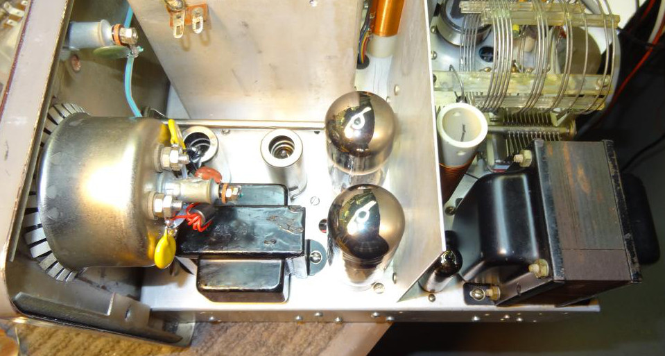
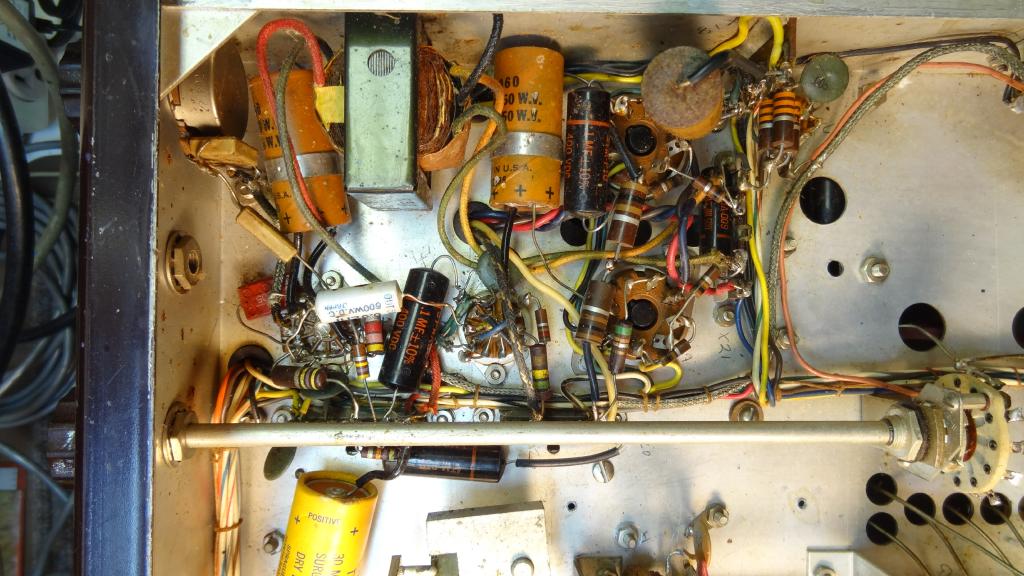 Original modulator section before it was stripped clean. The two big electrolytis on either side of the driver transformer will be replaced with two no bigger than your thumbnail, technology! The driver transformer was removed and replaced by a phase inverter. After taking it out I checked it and found it had an open winding.
The first thing I did was amass as much Ranger data as I could. Information came from the Internet, the manual, and publications like Electric Radio. There is no shortage of information and mods made by others. Studying all of this for weeks I formulated a plan of attack, what I would like to achieve in the end. Most of what I finally did is rehashed from previous published articles both in print and on the web but some things are unique to my restoration. I will list my sources at the end of this article.
One well known thing is the lack of efficiency and resultant heat in the Ranger. Back in 1955 no one cared much about energy consumption. You just threw in another resistor to lower the voltage. Obviously the 20K HV bleeder had to go. It draws 20 watts just sitting there whenever the rig is turned on. In the end a great deal of the rest of the original Ranger went also. I rebuilt the rig section by section installing new parts as I went along but the entire modulator section was removed. To make it easy I just clipped wires and took the screws out of the tube sockets and removed it as one big mass. My intent was to change to a phase inverter and change the modulator tubes so this drastic clean out of this section was warranted. It also gave me an opportunity to thoroughly clean the chassis which I did as I went along. I used Krud Kutter available at Lowes which works wonders for chassis cleaning. It is a green product but very tough against grease, grim, and nicotine. In some places I used q-tips or a small stiff paint brush to help get the dirt off. I sprayed the entire top of the chassis with Krud Kutter, used the stiff brush, and then rinsed with very hot water spray. Using hot water in a low humidity drys very quickly. Krud Kutter is compatible with many products but as with any chemical take care on something you are not sure of. I would not hesitate to spray it on a chassis but I would use it sparingly if at all on a front panel.
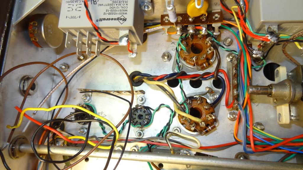
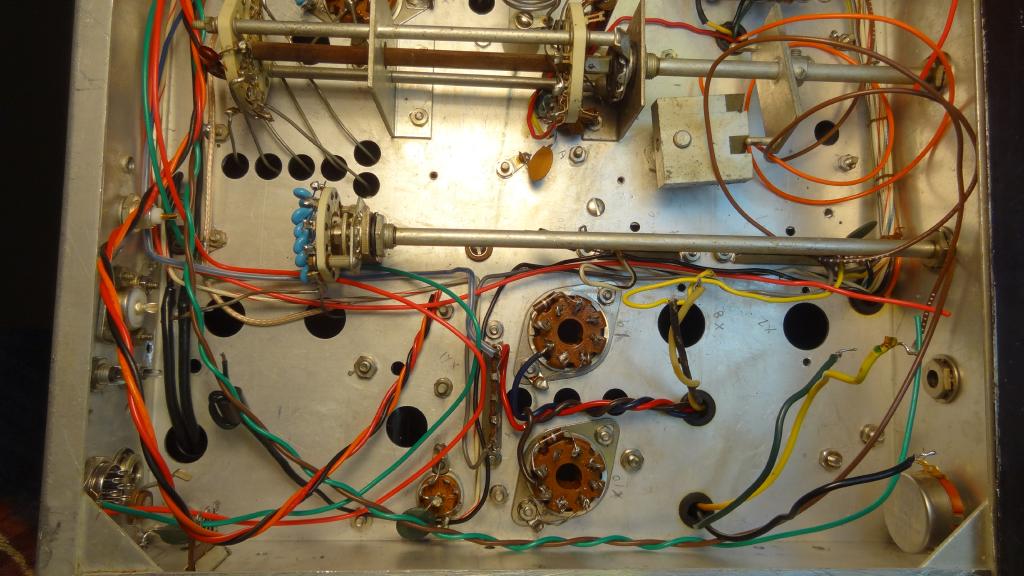 The cleaned out modulator section. Loading capacitors replaced.
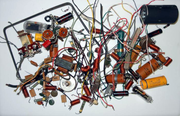 The final pile of parts removed from the Ranger. Not shown are the 1614 modulator tubes. The black shield at the upper right had been installed over the 6146.
Once I had an idea of what I wanted to do circuit wise I looked over my parts collection and ordered anything I might need to complete the project. No matter how big your parts collection there is always something you don't have. But Like any restoration project you never absolutely know what direction you will go in or what you will need until you are deep in the job. I changed directions on things several times in this project.
Here is the list of the things I did in my restoration/upgrade of the Ranger:
- Rebuilt the HV and LV supplies using high value electrolytics and minimal bleeders. Used solid-state rectifiers in plug-in tube bases for the high and low B+ supplies.
- Regulated the LV supply at 300V using a MOSFET. All low voltage is regulated.
- Regulated the VFO screen with a zener diode. The higher value dropping resistor and zener are located on the chassis bottom.
- Used a MOSFET to control the driver screen via the front panel drive pot.
- Used a 12.6V transformer off of the 6.3 line as an auto-transformer to develop 12 volts for the PTT relays and the bias voltage for the modulators. This is an early Ranger and has no bias windings.
- Installed an 8 pin mic connector wired for Kenwood (my standard here) with an 8 volt regulator for mics that need it.
- Used the 12V to supply high brightness LED's for the jewel power on and TX on indicators.
- Installed two relays for PTT including complete switching of both low and high B+, rear panel RX mute and Linear Key jacks, and antenna changeover. RX antenna BNC rear panel mounted.
- Installed a screw driver adjusted pot behind the crystal plug accessible from the front to control TX power. This controls the drive to the clamp tube which in turn controls the PA screen voltage.
- Modified mode switch connections to properly switch B+ and CW and AM modes correctly in conjunction with the PTT relay.
- Removed all Johnson line filtering and where necessary installed ferrite coils and capacitor filtering.
- Rewired much of the rig using Teflon wire.
- Added a back panel fuse and 3 wire AC line. Removed crystal socket AC output for external relay.
- Removed all wires from the back panel 9 pin octal connector but left it in place for possible future use.
- Completely rebuilt the modulator section using 7027A modulators and fixed bias. Removed the driver transformer and used a phase inverter and one stage of speech amplifier. Added a rear panel RCA jack for modulator scope output. Added a negative peak limiting circuit.
- Removed all Johnson “TVI” filtering and in some cases replaced with modern ferrite filters.
Now I will go on to describe these circuits in more detail. There are two schematics, one for all of the extraneous changes, and one covering the modulator section so you can follow along referencing the schematics and photos.
The original Johnson Ranger used choke input for both the high and low voltage supplies and a 10uf@700V on the high voltage and a 30uf@450V on the low voltage. I retained both chokes although the LV choke was opened in my Ranger. I ended up mounting a somewhat smaller replacement topside to leave room for more circuitry underneath. For the caps I used two 100uf@450V with 68K 3W equalizing resistors for the high voltage and one 100uf@450v with two 68K 3w resistors in parallel for the low voltage.
Both supplies have solid-state rectifiers mounted in tube bases in the original sockets. This makes it very easy to remove one or both to eliminate voltages during testing. The unused 5 volt winding used for the original 5R4 filament was rewired as a buck winding on the transformer primary. This helps to lower the AC input and since most line voltages are high today would probably be required in most all cases. In my case I also use an external 6/12V buck transformer in the 6V position. The Ranger was designed for no more than 115VAC to achieve the manual stated voltages. I use the measured filament voltage as a guideline. Under full load with an accurate AC voltmeter the filament voltage should be no more than 6.3 volts and preferably a few tenths of a volt less. I found that about 112-113 input volts to the primary brought it within this range.
Because I used high value bleeders to reduce heat and energy consumption the unloaded voltages tend to be higher than the values shown in the manual. The Ranger uses a choke input filter which requires a minimim current draw to keep the voltage from soaring. Without this load it acts more like a capacitor input filter. There is no problem with this higher voltsge as long as it does not exceed the ratings of the parts it is applied to in the unloaded state. The original Ranger used a 10uf 700 Volt high voltage filter so they had to use a bleeder that kept the unloaded high voltage below this value. Since I am using electrolytics with a total rating of 900 volts this should not be an issue. The high voltage is entirely switched by the PTT relay and then goes to the function switch for routing. Unloaded the high B+ is about 750 volts but could go to 800 volts depending on the line voltage. Under the clamp tube load (CW mode, key up) it lowers to about 610 volts. Key down at 150ma plate load lowers it to about 540 volts and on AM with an additional 130ma modulator load it only drops to 530 volts. The unload voltage is well within the filter voltage rating. You could if you wanted push this voltage up a little by raising the line voltage being mindful not to go much above 6.3 V on the filaments. The 6146 will easily take 850 volts but the modulators are usually the limiting factor. 7027A's will safely handle 600V with 300V on the screen and probably could even go a little more without problems. But there really is no logical reason to push it for the sake of a few extra watts that would not even be noticed at the receive end.
The low voltage supply is always energized on several circuits and is switched by the PTT relay to the clamp tube screen and in AM mode to the speech amp and modulator screens. The low B+ voltage before the regulator is about 370 volts with standby load and about 340 under full load. The regulator never has to dissipate a great deal of power, in the 1-4 watt area.
The low voltage is regulated with a MOSFET which is mounted on a small heatsink directly to the chassis. I used thermal grease liberally both between the device and the heatsink and the heatsink and the chassis. The device specified is electrically insulated so no washers are needed. These are tough devices but some precautions are needed. It is rated at 800V@11A but the gate to source voltage is 30V maximum. This is why they are so sensitive to static out of the circuit. In the circuit I use a zener from source to gate to protect the junction and also a pass diode to the load. This prevents any return current from external capacitors, etc. from back discharging through the device. You could also put this diode in the other direction from drain to source to discharge around the device, either way works and actually the device has this diode built-in. I just like to be extra careful.
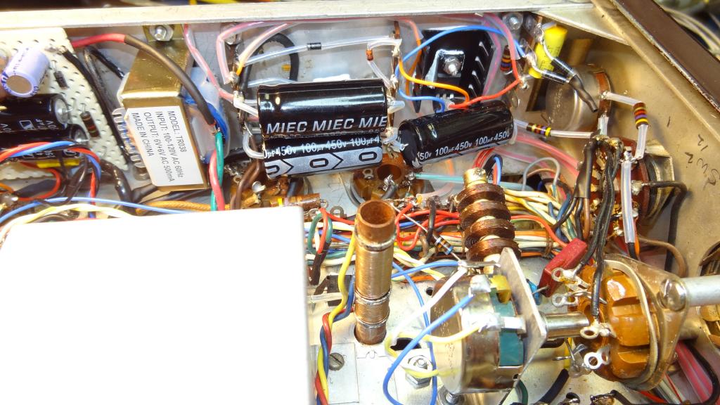 The new power supply section. To the far left is the Bias and PTT board, then the bias and 12V supply transformer, the low and high B+ filters, and the 300 Volt regulator. The replacement drive pot mounted in the front panel and in the foreground is the power level pot behind the crystal socket.
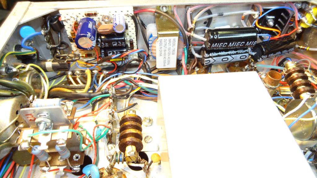 Better view of the bias and PTT board, the line fuse and filter, the rear panel bias pot and modulator scope jack, and the screen voltage circuit mounted on a vertical aluminum plate.
The OA2 gas tube was removed in the VFO and a wire was tacked to the output pin of the tube to the VFO screen and routed to below the chassis. No other changes are needed it the VFO. Removing the tube disconnects the existing dropping resistor. The new regulator is a zener mounted at the front center under the chassis on a three terminal strip with a 33K 2 watt resistor.
Another area that is often a problem in the Ranger is the driver screen control. It is a large 4 watt pot mounted on the front panel. Mine was open which often happens. The original circuit had at least 4 watts going through it probably more at high line voltages. I tried mounting a smaller pot and resistors on the high and low side but it still drew way too much power. I ended up using a MOSFET mounted near the driver tube and a 1 meg pot for the driver control. It has less than a milliamp going thru it and works very smoothly.
 The VFO screen regulator zener and dropping resistor mounted below chassis and the output power pot mounted on an aluminum strip behind the crystal socket.
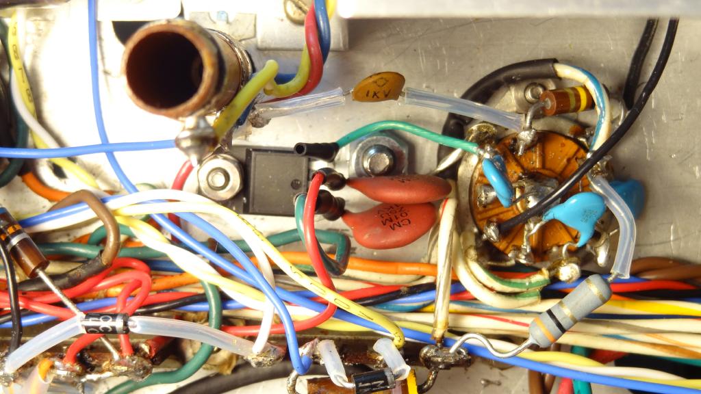 View of Driver tube MOSFET screen control. Wiring not re-laced yet.
I had a number of relays from a prior project at my former company. They are sealed, 12 volts, and DPDT. I had used then before in my home-brew Multi Elmac power supply and they worked well so I decided to use two in the Ranger. This meant I needed 12 volts DC and also the bias voltage for the modulator. My Ranger was an early one that used cathode bias in the modulator and had no taps on the power transformer for bias. I thought about the different methods to achieve this and I decided to try a 12.6 volt 500ma transformer wired as an auto transformer from the Ranger 6.3 volt filament line. This worked well giving me about 14VDC and over -100 volts unloaded. I mounted the transformer on the side panel and next to it a perf board with the components for the PTT and bias supply. The PTT is keyed through a MOSFET and only a few milliamps at 12V appears at the microphone connector. 12V is also supplied via a dropping resistor to the left front panel jewel on the VFO bezel for power on indication and to the right jewel when PTT is keyed. I used a high output LED and carefully filed the inside of the jewel shaft to accommodate the LED. The bias voltage is regulated with a zener to -56 volts and sent to a rear panel pot to adjust the modulator bias. There is also an LM317 regulator on this board to supply -8 volts to the 8 pin microphone jack which is wired for the Kenwood standard.
 Closeup view of the Antenna Relay. All internal shielded cable is RG316 Teflon.
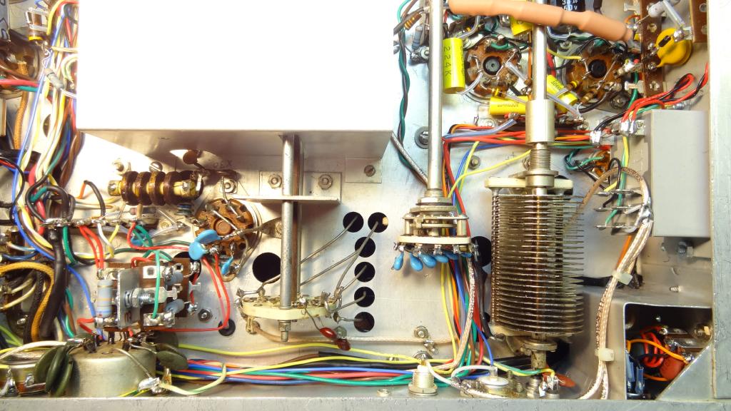 View showing the rear of the completed modulator section, the antenna relay, the reduced size shield around the microphone and key jacks, the rear panel receive antenna (BNC), the new loading capacitors, and to the left the PA screen resistor assembly. The 9 pin octal connector remains but has no connections. The cables are not re-laced yet.
I decided to retain the 6AQ5 clamp tube rather than use fixed bias on the PA as was described in the July 2011 ER article. My reasoning was that I could very easily install a pot behind the crystal socket, accessible from the front panel, to adjust the final PA screen voltage and thus set any output power level I desired. This is especially useful for driving a linear. The pot is the same value as and replaces R37 in the PA grid circuit. The clamp tube is normally in cutoff during no or low RF drive reducing the final PA screen and protecting the tube. With this pot you can fool the clamp tube and manually reduce the PA screen voltage and the RF power out. This works very smoothly and allows a full range of output power settings. The clamp tube works normally on CW and with the PTT unkeyed there is no PA plate voltage or clamp tube screen voltage and thus no energy dissipated. The clamp screen resistor is a 10K 3W fed from the 300V regulated supply through the PTT (power) relay.
 The new modulator section topside. The low level tubes sockets were replaced with shielded sockets, the modulators are 7027A's. The meter has ferrite filters on the leads. All new wiring is Teflon.
 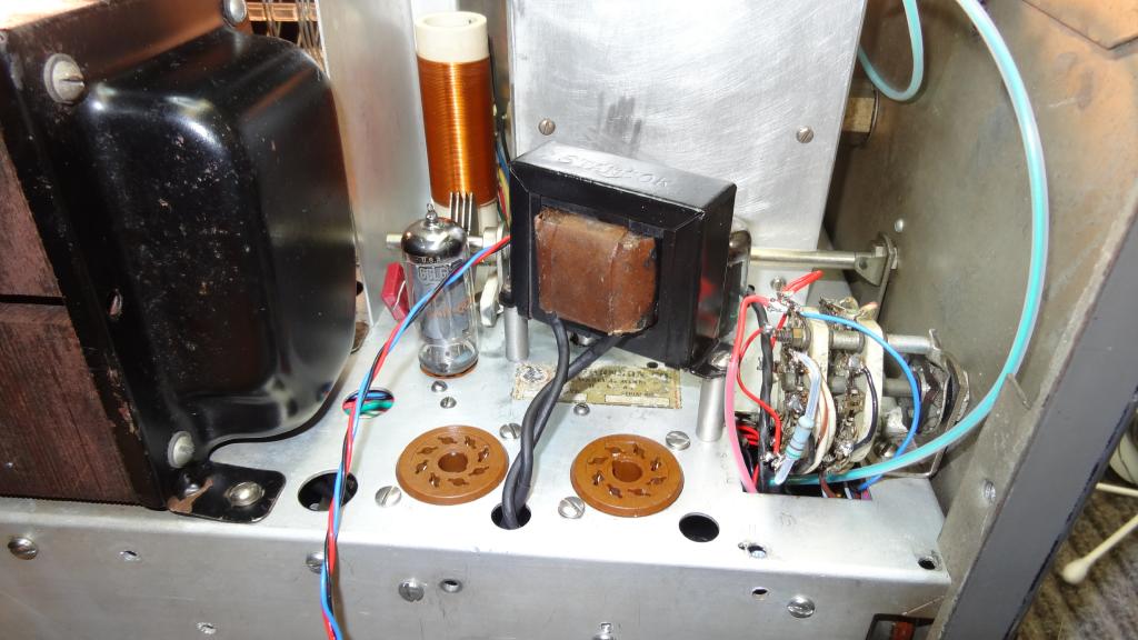 View of the topside mounted LV choke on standoff's. The plugin solid-state rectifiers are removed.
The change to switching both the high and low (to selected stages) B+ necessitated a change in the way the function switch operates. I thought about this for quite awhile, tried many schemes, and finally came up with rewiring the switch and using diodes to achieve the desired result. The switch has five positions and one must work around the confines of the existing wafer. This made it difficult but in the end I had almost exactly what I wanted. You want the switch to turn on the Oscillator and buffer stages in the tune position so both are grounded through diodes. On AM you want both to be grounded but only when there is PTT. On CW you want only the buffer to be grounded during PTT. The schematic shows how this was achieved. Refer to the original Ranger schematic to cross reference pin numbers. The lead from pin 6 of SW4A is removed from the PA screen and grounded. You could also remove this wire and ground it at the switch but the pin is a little hard to get to. This switched ground on the PA screen is no longer needed as the high voltage is switched through the power PTT relay. Using this pin made it possible to wire the switch in the correct configuration and switching the HV B+ made it possible to use this pin. It was nice how things worked out this way in the end. Something I could not have planned on in the beginning.
There is no B+ voltage on the function switch when the PTT is unkeyed. It is good practice to not change switch positions when keyed. This helps to save the contacts on the switch. I had to come up with a new wiring scheme on my Ranger mode switch as the HV (position 10 SW4B) tab was burnt off. I could have taken it apart and replaced the pin but I found that the unused tabs on the other side of the wafer that had previously switched the 6.3 VAC to the transmit pilot light worked well when wired properly. Hopefully you won't have this issue but it shows how you can be creative to solve the problem if you do.
Also see Ranger revision notes regarding the function switch below.
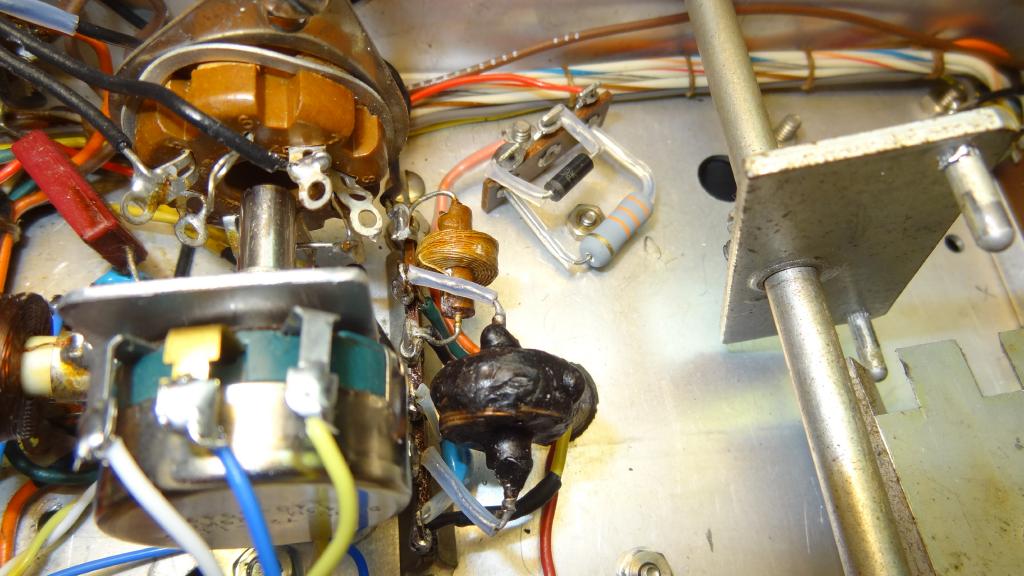
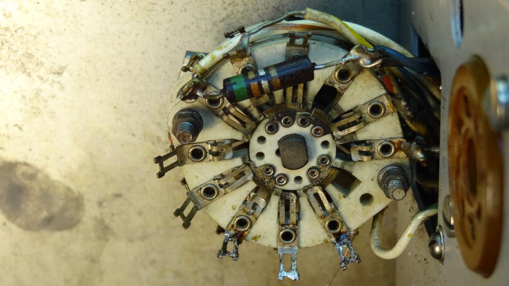 The function switch showing the burnt and missing contact and poor original wiring
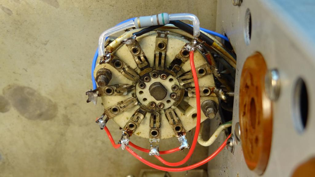 The solution was to use the contacts on the others side of the wafer which had previously been use for the transmit front panel indicator now controlled by the PTT.
Referring to a September 2011 ER article on the Johnson TVI filters I decided to remove all of the filters. Some were air coils and others were molded inductors. This makes a great deal more room and much cleaner looking chassis. As was pointed out in the article the original filters looked good and probably sold rigs but had limited value as actual filters. Johnson also went way overboard filtering things like the pilot lights. I did put filtering on a few things using ferrites like the AC line, the microphone connector leads, the Key lead, and the Meter. Th meter is another thing that is probably not necessary but it was easy to do so I did it. Also a very important update is to but back to back diodes across the meter for protection.
I rewired about 40% of the Ranger with Teflon wire using a combination of mostly #22 and some #18. In my opinion Teflon is much easier to work with and so nice to solder. Nothing melts and if you accidentally brush against an adjacent wire there is no problem. I didn't wholesale replace existing wiring but if I happened to be working on a wire and I had easy access to both ends and it was a higher voltage circuit I usually replaced it. As part of the rewiring cleanup process when I removed an existing wire from a connection and I was not replacing it with Teflon I would slip a short piece of heat shrink over the end to clean it up before I reinstalled it. The antenna, microphone, and modulator scope takeoff were all wired with RG316 Teflon coax. Again a dream to work with.
I installed a new three wire AC line cord and back panel fuse (3A) This was mounted in the area of the removed crystal socket AC relay jack. What were they thinking back then? No grounded AC, fuse in the neutral, crystal socket AC, no GFI's. It is a wonder more people weren't killed!
The modulator section was completely rebuilt. I used ideas from many sources including my design that has worked well in my Multi Elmac A54/AF67 restorations. I decided to use 7027A's mainly because I had them and I also had spares. I felt the 6L6 series was a little under rated for the Ranger plate voltages and longer tube life. The original 1614 would be a little closer to being OK but I did not have any spares and it is unlikely there are many NOS of this tube available, they certainly are not being made anymore. I gutted the entire modulator section including the driver transformer. I had a Ranger that had used cathode bias and I am now using fixed bias with the bias pot on the Ranger's rear panel.
 The beginning of the modulator section construction. All filament wiring is twisted pair with no common ground within the modulator. The power relay is mounted but not wired.
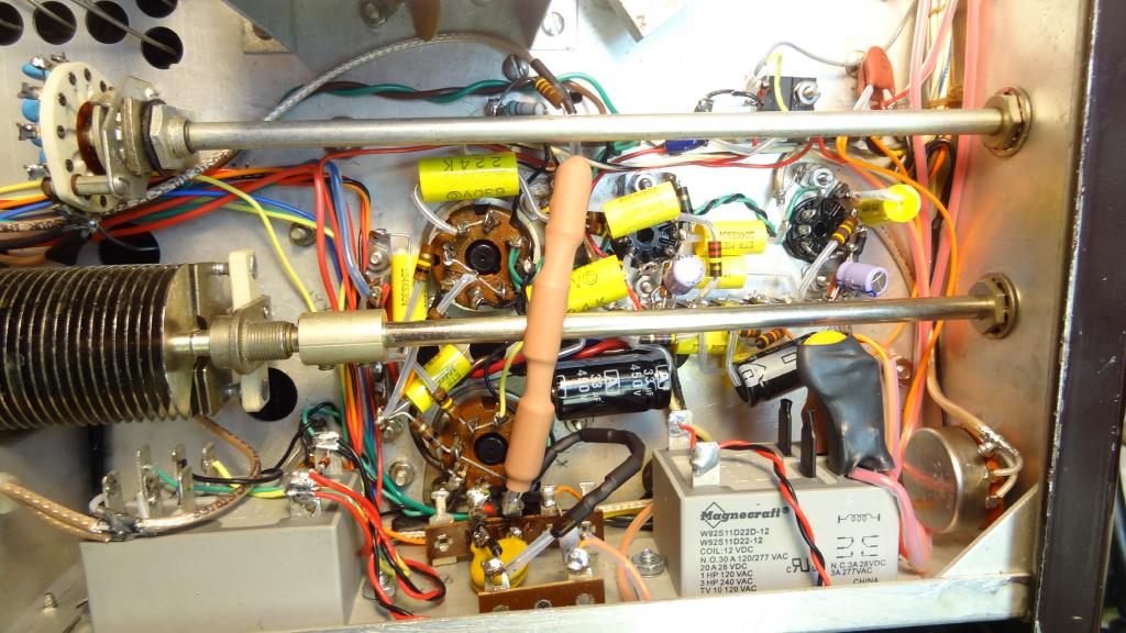 The completed modulator section. The brown heatshrink tube is the scope dropping resistors and the small black heatshrink tube is the zener negative peak limiter. The two PTT relays are shown, antenna on left and power on the right. At the upper right is the chassis mounted keying FET.
The speech amplifier is one half of a 12AX7 feeding a 12AT7 phase inverter. One half is additional amplification and the other half is used as a phase inverter feeding the grids of the 7027A's. I retained the modulator secondary shunt capacitor replacing it with a .02uf 2kV ceramic. The original 9 pin sockets were replaced with shielded sockets and shields. All other components are new including the front panel Microphone level control which was bad in my Ranger. The filament circuits were fed with twisted pair wires from the Ranger filament bus. No filament grounding takes place in or near the modulator section.
 The PA screen resistor assembly. Mixes 60% modulated and 40% unmodulated screen voltage.
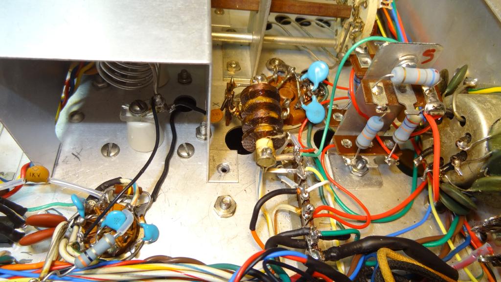 The PA screen assembly mounted.
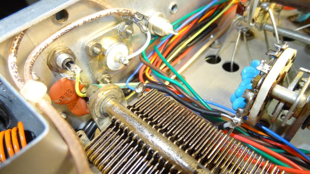 Closeup view of the TX and RX antenna connectors, the RX mute and amplifier key connectors, and the cleaned up loading capacitors.
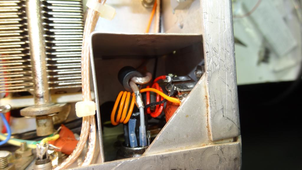 Closeup view of the microphone connector and filters and the modified aluminum cage.
A note on replacing the front panel pots. There is a nut between the chassis and the front panel but you do not have to remove the front panel to replace a pot. Remove the knob and nut on the outside of the front panel and after removing the wires from the pot you can unscrew the pot. You may have to cut the pot leads off close to the body to be able to turn the pot out of the captive nut. Do this with the chassis sitting on its rear, front panel up so the internal nut does not drop away from the opening. Install a new smaller pot in reverse You can use a smaller pot for the drive control if you use the MOSFET circuit as described above and shown in the schematic. The audio level pot can always be smaller.
Also added to the modulator were a negative peak limiting circuit and a resistor divider and rear panel jack for modulation scope monitoring. I decided to use the simpler series zener diode approach. I had done this way in my Multi Elmac AF67 and A54 and it worked well. I added a circuit based on an article by WA1KNX on mixing both modulated and unmodulated voltage to the PA screen.
See - AMFONE Topic 32893
 The rear panel. Left section - Microphone and key jacks, RX mute and amplifier key jacks, and TX and RX antenna jacks. Right section - 9 pin octal (not used), modulator bias, modulator scope out, fuse, and line cord. No case modifications are necessary for the new connectors.
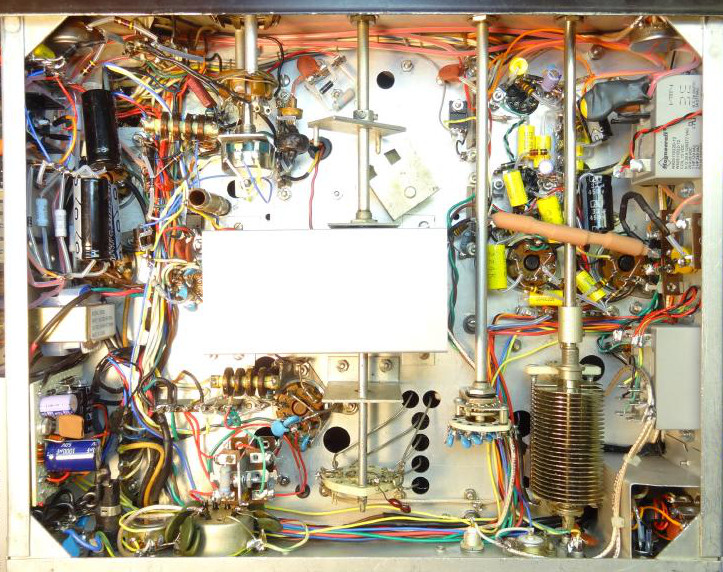 View of completed under chassis. Wires not re-laced yet.
As was mentioned earlier I added a +8V regulator to supply voltage to the microphone jack. I did not multiplex it onto the microphone lead but I do connect it to pin 5 of the microphone connector which is the Kenwood standard. Most all manufacturers have standardized on +8 volts at the microphone jack. I use it for a source follower FET in my D104 which supplies a high impedance to the microphone element when used with low impedance rigs. Because I use a very high resistance grid leak in the Ranger it would not be an issue to hook a D104 directly to the input but if you had the source follower it might be better to use it and keep the transmission impedance lower on the microphone cable.
I am still in the process of getting the Ranger back in the case but that might take awhile. I would like to thoroughly on air test it before wrapping it up. So far I have gotten excellent on air reports. The cathode keyed CW note is good. I see no reason to install the keyer circuit especially since I am only an occasional CW operator. Modulator bias for the 7027A's is set to about 70ma which corresponds to about -29 volts bias. RF power out is about 45 watts.
I was also just offered a free Ranger so I am excited to see how that looks. If it has a better front panel then the one I have I may swap. I will update here when I have new information to publish. I would be glad to answer any questions, just email me. My QRZ email address is good.
Some additional notes regarding Ranger revisions.
The Ranger apparently had a number of revisions. The ones we readily know about are the addition of a keyer circuit, which added a negative bias supply that was also used to supply fixed bias to the modulator grids in lieu of the cathode bias in earlier units.
One other thing that was changed that may not be as apparent is how switch SW4, the function switch, is wired. The early models switch the high voltage to the PA plate and screen and modulator plates. HV enters switch SW4B on pin 10 and exits on pin 9. HV is switched to the PA plate and screen and modulator plates only in the AM and CW positions of the function switch.
Later models of the Ranger and the Ranger II had no pin 9 contact on switch SW4B and no connection to pin 10. The solder connection on Pin 9 was used as a tie point for the plate/screen current shunt (SH4). This configuration of the Ranger left the HV B+ engaged to the PA plate and screen and the modulator plates at ALL times. In the tune position (and also the off position) of the function switch the PA screen is grounded thus eliminating the PA from operating even though it has plate voltage applied. The PP modulator screens are only energized in the AM position of the function switch.
The way my modifications are made were based on the early Ranger. As noted in the photos and description above I used contacts on the SW4B pins 1-6 side to implement the early style HV B+ switching in the AM and CW positions. This was really redundant as I also switch BOTH the HV and LV B+ with one of the PTT relays. This negates the need to ground the PA screen in the tune position on SW4A. I use those contacts, as shown on the schematic, along with some diode logic to switch the modes. Switching the HV with both the function switch and the PTT relay, although somewhat redundant, does make things work more logically.
Although there are plenty of Rangers out there that have the HV energized at all times I prefer the switching method. Keep in mind that the rigs that do not switch the HV have HV B+ on the rear accessory connector at all times when the rig is turned on.
This is confusing because some models that had the keyer modification had the SW4B change and some did not. It is not clear exactly when this change was made in the Ranger production. The two Johnson schematics listed below show the two wiring methods for SW4.
So why did Johnson make this change? My best guess is that they had failure problems using the small wafer switch contacts to “hot” switch 600 volts at 200ma. If you look at the early schematic you will see an RC circuit made up of R34 and C76 which apparently was used to suppress contact arcing on SW4B. I would not recommend using the old switching method or rewiring the switch to use the old method unless you also switch the HV B+ ahead of SW4 as I do in my mods with the PTT relay. When wired in this way the function switch should not be moved when the PTT is engaged.
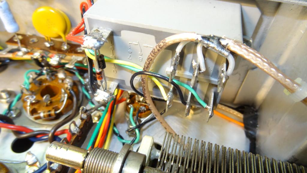
 The completed under chassis with harnesses relaced. Note the addition of an RF choke from the RF output to ground, another safety feature.
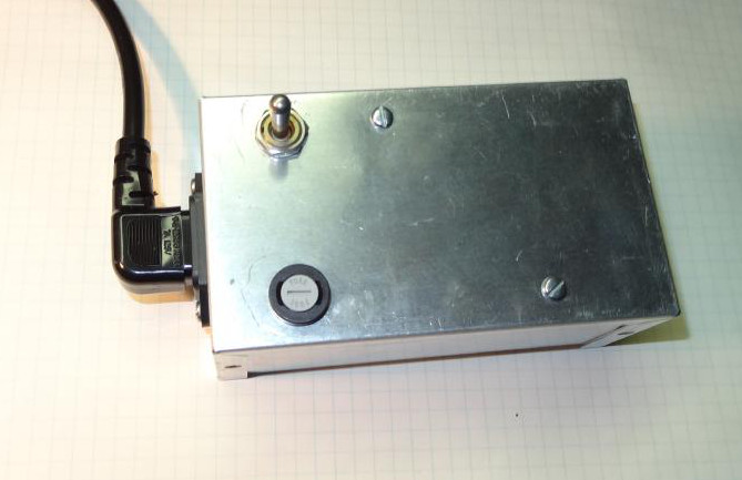 As mentioned I used the former 5V rectifier filament winding to "buck" the line voltage but in some cases more line reduction is needed.
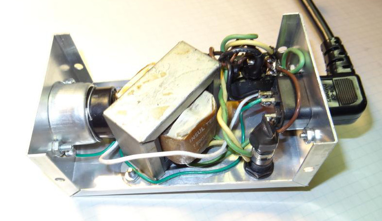 This simple box uses a 12.6V 2A transformer to "buck" the line voltage by an additional 6 or 12 volts. The toggle switch has a center off position. Monitoring the filament voltage with an accurate AC meter is a good way to set line voltage. I like to see 6.0 to no more than 6.3 volts.
Some late Notes
Some time has gone by since my last update here and I had still not installed the Ranger back into its case. I was waiting until warm weather to paint the dial cover outside. Then after it was painted other things came up and it was months later until I got to finishing things up. After I reinstalled the dial cover I wanted to calibrate the VFO so I readied the test equipment and warmed everything up. While going through the procedure I discovered that there was slippage in the tuning. Larger excursions would work but while trying to make small tuning changes it would shift all over. I took the side cover off of the VFO and I could see that the VFO tuning capacitor was slipping. Carefully inspecting the shaft it seemed that just the capacitor was slipping. I could see the set screws but could not get to them from the side panel. If all else fails go to the assembly manual, so I did and it explained that there was an access hole in the chassis below the VFO to tighten the set screws. Unfortunately it was the back two set screws that needed to be tightened and I could not line up a screw driver through the existing hole. I drilled another hold behind it and I was able to successfully tighten the screws. The VFO was calibrated and all was well.
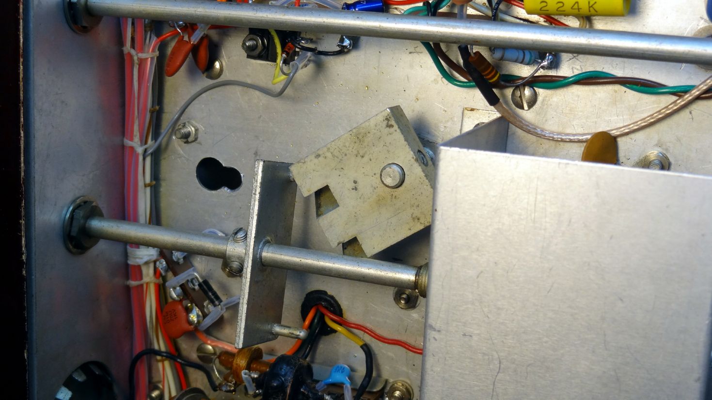 Access hole for tightening the VFO coupling. There are two sets of screws. A front pair and a rear pair. I had to drill
an additional hole for easy access to the rear pair.
Access hole for tightening the VFO coupling. There are two sets of screws. A front pair and a rear pair. I had to drill
an additional hole for easy access to the rear pair. The Ranger sits proudly among the other HF rigs at my studio A operating position. It works well in conjunction with the Heath SB200 amplifier loafing along at about 15-20 watts drive or I can use it barefoot with 50 watts output.
Schematics and Reviews
- Original early version Ranger schematic
- Ranger Operating Manual - later schematic
- Ranger Assembly Manual
- Mid 1950's Johnson Ranger catalog page
- E.F. Johnson inside catalog cover - "Amateur Radio is Fun"
- WA3DSP Ranger Modifications Schematic, all except modulator section
- WA3DSP Ranger Modulator Modifications Schematic
- QST Review, The Viking Ranger, September, 1954 QST, Recent Equipment, Pages 42,43 - available at the ARRL web site
Some resources that I used during this restoration -
Parts used
Besides the normal resistors, capacitors, diodes, etc.
- PTT Relays - Magnacraft W92S11D22D-12D
- MOSFET LV Regulator, Drive control, Keyer - 511-STF11NM80 STMicroelectronics - 11A 800V
- MOSFET PTT - 512-FQP8P10 - Fairchild - P channel 100V
- Regulator LM317A
- Bias and PTT transformer - Philmore TR038 - 12VCT 500ma
Parts Reference
- Mouser - relays, resistors, capacitors, MOSFET's, zeners
- Fourmost – Replacement coaming for VFO bezel – FOR120 (large)
- Barno Electric - TR038 filament transformer
- Apex – Teflon wire and tubing, coax, surplus electronics
Circuit and Design References
- W8JI - another take on Johnson audio mods
- AD5X - good mod ideas
- W3AM - Turbo Ranger AM mods
- Microphone connection diagrams
- Amidon - Ferrite cores for RFI suppression
- Probably a worthwhile mod even if you don't have the problem.
- Zener negative peak limiter.
- Electric Radio Magazine – July 2004, July 2011, September 2011 Issues
- The Amateur Radio Handbook - multiple years
- RCA Transmitting and RCA receiving tube manuals
Chemicals Used
- Plasti-kote GM7191 Touch up Spray - matches dark maroon Johnson color - available HERE (as of 2/2013)
- Krud Kutter
- Deoxit D5
- Deoxit gold
- WD40
- Windex (The Greek wedding miracle fluid!)
I give full credit to those whose ideas I have used in this restoration and upgrade including N2NIR, July 2011 ER; Ben Greathouse, September 2011 ER; AD5X; The AM technical Forum; and W3NE, Bob Thomas who is also restoring a Ranger and gave me moral support as well as critical analysis. Hopefully some of my ideas will also be useful to others. The Ranger is a great little AM rig. My intent was to make it better - more energy efficient, more reliable, safer, and especially more fun to use. I feel I have accomplished those goals. Talk to you on the air. 73, Doug
I have made an attempt to present my work here so that others could benefit. Hopefully I have written an understandable document. I welcome constructive criticism. If you don't understand something I would be more than willing to answer any questions you may have. Just email me at my QRZ email address.
This page last updated 1/31/2014
© 2012 - WA3DSP