Collins Restoration Notes from WA3DSP
75S1 Receiver Updates HERE
Modernizing the Collins 516F-2 Power Supply
The Collins 516F-2 Power Supply is used to power the Collins 32S transmitters and the KWM2 transceiver. It supplies the 6.3 volt filament, low and high voltage B+, and bias voltages. The original design used a 5R4 vacuum tube rectifier for the high voltage B+ and a 5U4 for the low voltage. The bias supply used an encased selenium rectifier. Mains AC was routed to the transmitter or transceiver where a switch was used to turn the power on.
My 516F-2 was completely stock and in excellent condition. It did not include a speaker. In reviewing the many Internet sites about upgrading and restoring the power supply I decided how I was going to proceed. I wanted to reduce heat, increase efficiency, and improve reliability. One consideration was my local line voltage which is consistently on the high side running an average of about 123 volts but as high as 128 volts at times.
This article is about my upgrade of the Collins 516F-2 power supply. It includes four separate changes which could be made individually or in entirety to make the supply and the equipment it works with more reliable. The changes are:
- Removed the rectifier tubes and used the unused 5V windings to buck the primary
- Installed a SSR to eliminate the turn-on current through the equipment power switch
- Installed a voltage regulator to give constant +270VDC low B+
- Installed a small 12V muffin fan run from rectified 6.3VAC to cool the bleeder cage.
Being an enthusiast of vacuum tube equipment made before 1970 I have a real concern with elevated line voltages and its effect on this equipment. I did some research on this topic and I found that nominal line voltages increased from something less than 110 Volts in the early 20th century to usually greater than 120 volts today. Several ANSI documents1 describe the dilemma that electrical engineers had with standard voltages in the evolving US electrical system.
If you are a collector of older electronic and electrical equipment like I am then you have more than likely seen equipment labels specifying 110V, 115V, 117V, and 120V as the operating voltage. In the 1950's when the Collins S-line was designed the nominal line voltage was 115V but there is a wide range of minimum and maximum voltages around that nominal value. Today national standards2 classify two ranges. (A) with a range of 110-124.5 volts or roughly +-5% of nominal or (B) with a range of 108-126 volts or roughly -13% to +6% of nominal. Range (A) is considered normal and voltages outside of these limits should be infrequent. The (B) range is considered out of limits if encountered on a sustained basis and corrective action should be taken. There does not seem to be any clarification of the terms infrequent and sustained so I suppose there is some room for interpretation here.
So typical line voltages can be anywhere between 110 and 124.5 volts and be considered normal by your utility. In my practical experience and talking to many other hams line voltages are often on the high side of this range. I have been recording line voltage samples at my home every 10 minutes for several years and looking back through the data my lowest voltage is about 120 and highest about 128 with the average about 124. I would probably have an argument for being in the (B) range in many cases. My line voltage does have fairly good regulation as these numbers do not change substantially from summer to winter or at different times of the day.
So that leads me back to the Collins 516F-2 power supply. I had a KWM2 and recently acquired a 32s1 and 75s1 pair. In measuring the stock supply with no modifications the low B+ when using the KWM2 in receive mode was greater than 290 volts and often close to or slightly more than 300 volts. If you have a KWM2 you and you have puttered around inside after it has been on for awhile you know that many of the tubes run extremely hot. So hot in fact that touching them can cause almost instant burns. I was not happy that the higher B+ and filament voltage were de-rating the life of the tubes, causing additional heat, and generally wasting energy.
I also intended to solid-state the 5U4 and 5R4 rectifiers which with lower voltage drop would add to the problem. So my first modification was to remove the vacuum tube rectifiers and build solid-state replacements on plug in sockets. I then used the former 5 volt filament windings in series to buck the line voltage. This gave me 10 volts less line voltage and with my 124 average line voltage it brought the 516F-2's applied primary voltage within specs. This resulted in filament voltages, measured at the tube socket, of about 6.1 volts AC and well within specs on the low side, just where I wanted it. However the low B+ was still too high. A common fix for this is to add series resistance in the output of the rectifier diodes. This somewhat solves the problem but greatly reduces the regulation. The KWM2 draws significantly more low B+ current on transmit than receive thus adding a resistance that gives a satisfactory receive voltage results in a too low B+ on transmit. The 32s1 is similar. When in standby there is very little B+ draw but the voltage still appears on many tubes and components. Because of this very light load the low B+ can exceed 300 volts by a substantial amount. For me it was just not a good solution.
I scouted around and asked some questions on various forums and I found that Clarence Watts W6BN (now W7ASB) had designed a MOSFET regulator for the 516F-2. I used his design and added a few more safety features. With this regulator you can set the low B+ to whatever you want. Collins specifies +275 volts but I choose +270 for my supply and it works well with both my KWM2 and the 32s1. I did add an additional 100 ohm series resistor off of the diode rectifiers which I located in the bleeder cage on the top of the chassis. To change the output voltage you select the reference zener voltage applied to the MOSFET gate. In my case I used two 100 volt and one 75 volt zener in series. Using this regulator results in the B+ being within a few volts of the set voltage independent of the load. The equipment never sees more than 270 Volts.
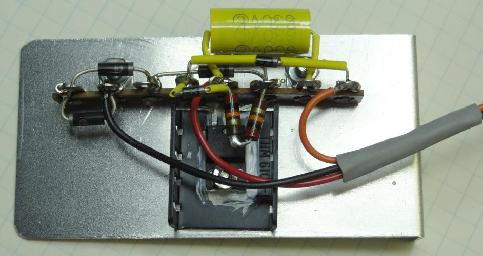 View of the completed MOSFET regulator ready for installation
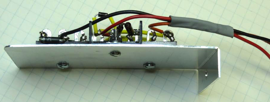 Side view of regulator panel showing mounting flange at bottom
I did not pay much attention to the high B+ as this is much less critical and would be impractical to regulate. The parallel resonant circuit of L1 and C1 (.05ufd) is meant to somewhat regulate the loaded to no load voltage. Theoretically at 120hz (60hz line) the parallel resonance happens at no load or just bleeder load and results in a reduced output voltage. In my tests this was the case. Without C1 the no load high B+ was well over 1000 volts. With it installed it measured around 900 volts. C1 is often removed after a failure as an unnecessary part but without it the stresses on the high B+ components could result in a failure. If you are using the supply on a 50hz line the value of C1 would need to be changed.
The bias voltage selenium rectifier was replaced with a diode rectifier. Later supplies have a diode rectifier and it generally does not need to be replaced.
I also wanted to eliminate the high AC current through the connection to the rig and its AC power switch. I reviewed a number of methods to accomplish this. Most involved relays and power sources that need to be on all the time. Some used a 120 volt mechanical relay to switch the power. This was probably the simplest approach but since I did not have a 120 volt AC coil relay I decided to go in a different direction. I did have a number of solid-state relay (SSR) modules on hand. They were rated at 12 amps and required anywhere from 3 to 30 volts DC at about 10 ma. to operate.
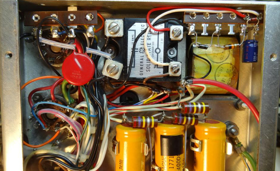
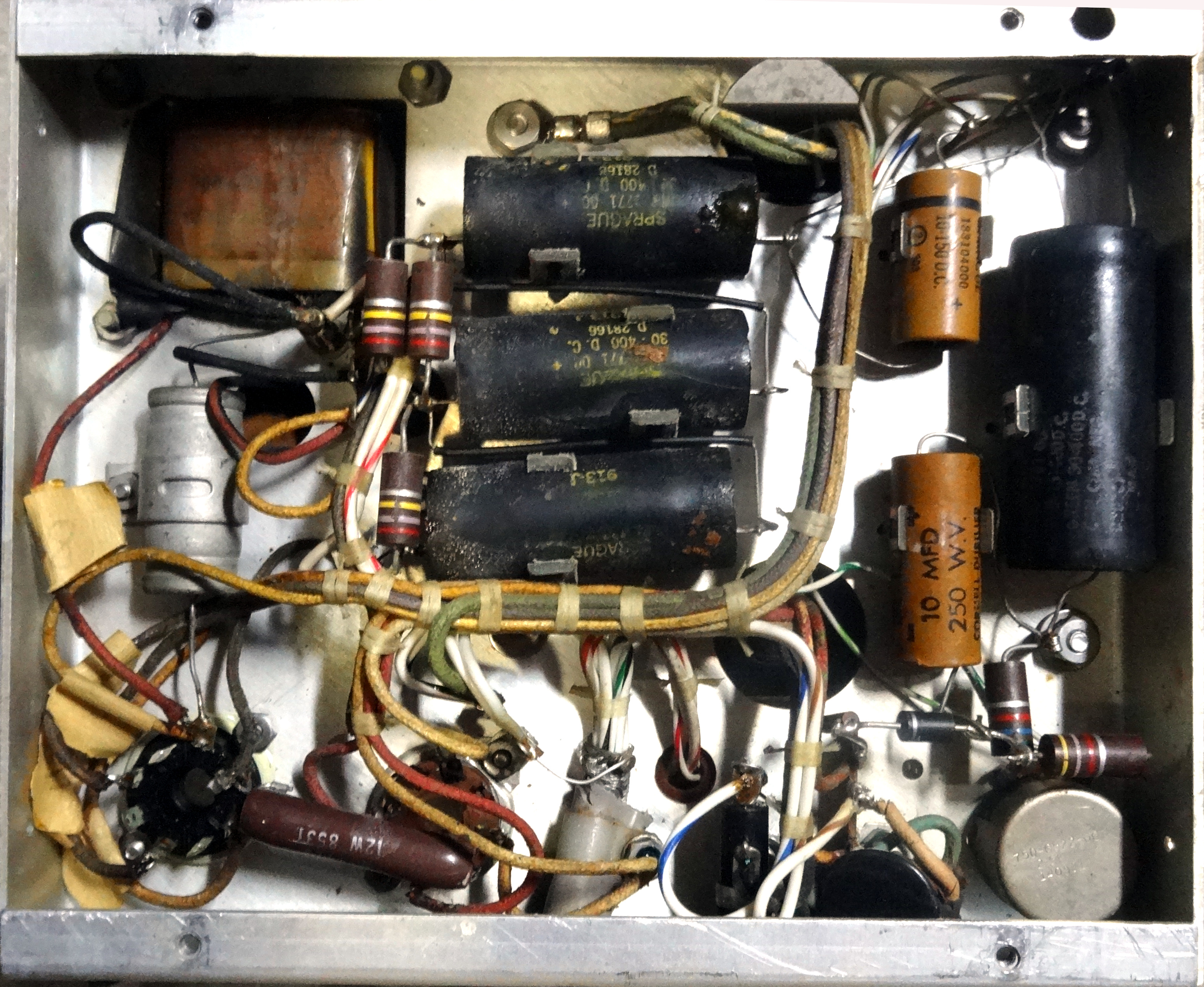
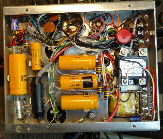 Photo showing entire bottom of chassis. Replacement C1 is remounted to lower left in heat-shrink, Fan rectifier at upper left, SSR and components at right
The module as you can see in the photo fits nicely in the area where C1, the HV choke resonating capacitor, had been mounted. C1 was remounted on the front right side of the chassis. It is a replacement glass high voltage capacitor with heat shrink tubing over it. The circuitry includes a resistor, diode, capacitor, zener diode, and the SSR module. SSR�s have very high isolation between the switching and switched terminals but in this circuit the AC is NOT isolated. I did not want to use a separate power source which would be on all the time so instead I opted to directly rectify and filter the line to drive the SSR through the switch in the rig. This greatly reduces the current through the rigs power switch from amperes of current to less than 20 ma. and when the power switch is off there is no current flow from the AC line. The series resistor needs to be selected based on the turn-on current requirements of the selected SSR.
 View of the SSR and associated components. Six terminal strip mounted at upper right for SSR components and four terminal strip at upper left for wiring of 5 volt filament windings primary buck circuit.
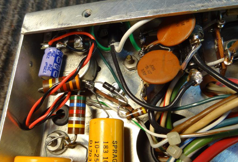 Three terminal strip mounted at upper right for fan rectifier and filter
Because there is high voltage present around the solid state rectifiers and regulator I installed an aluminum plate on the back right opening of the case as protection. In a discussion wiith Bill Carnes he mentioned that there was often a heat problem with the 516F-2 power transformer and that possibly this plate would interfere with airflow. I did not see a problem with that as there is ample opening on the outter case and the rear is still well opened. I did however find that the after awhile the bleeder resistor cage in the back emitted a great deal of heat. While the majority of this radiated upwards the cage is right up against the power transformer and appeared to considerably heat the back side. I experimented with a small 12 volts computer size muffin fan mounted blowing out on the back of the cage and running on about 6-7 volts DC. It worked very well in keeping the cage cool and was extremely quiet. I permanently mounted it with two 4-40 screws, nut side out, to the back of the cage. Power was procured from the 6.3 VAC bus a half wave diode rectifier and a small filter capacitor.
 Views of the regulator and fan modifications with protection plate mounted on the back before mounting in the case.
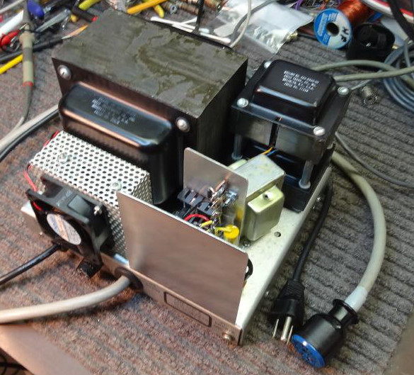
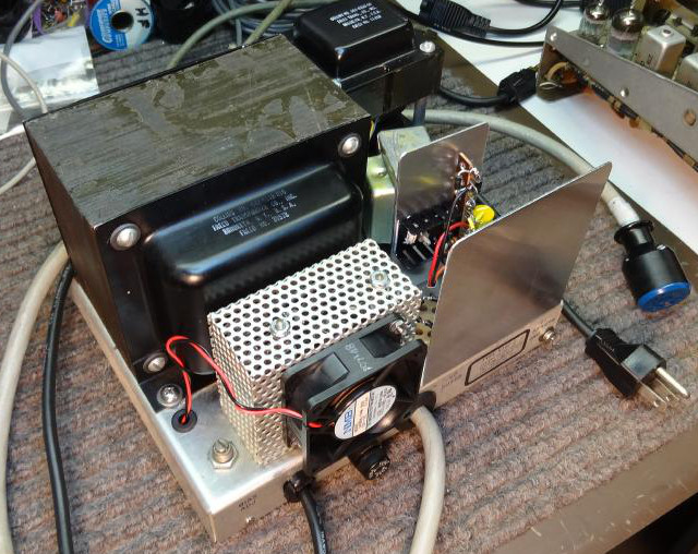
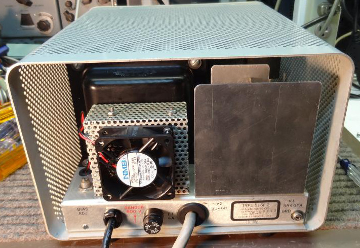 Rear view installed in it's case showing the fan mounted on the bleeder cage and the protetion shield at right.
The completed supply works very well with both my KWM2 and 32S-1 and I am happy knowing that they have a constant and reasonable B+ voltage. While I am sure there are many who are abhorred by the thought of making any changes to this classic equipment this is certainly your choice. I just wanted to raise the awareness that using this power supply or other classic equipment on today's power grid without some means of voltage compensation could lead to premature failure of associated components. If you do nothing else use an external variac or buck transformer to ease the problem.
- 208 Volt Systems and American National Standard C84.1
Text of ANSI-C84-1-2011 - Explanantion of voltage_tolerance in US secondary power systems.
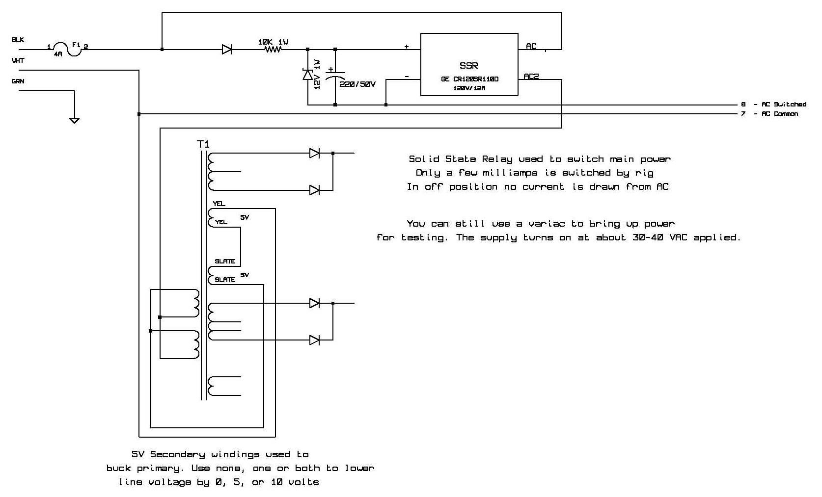
Simplified schematic of the power-on modifications. Refer to the complete modification schematic for more detail.
This supply still has the original electrolytic filter capacitors which are working fine but if and when they need replacement I will likely replace the three 30uf/400 volt high voltage stack with three 100uf/450 volt replacements. The higher values are now smaller than the original 30uf capacitors. I would do the same in the low voltage supply replacing the 15uf and 30uf capacitors with 100uf 450 volt values.
Another 516F-2 Update Example
Ten years after my original 516F-2 update I just did another one in 2022. The modification were similar but I did change out all the electrolytics as the old ones were very "ratty" looking. In doing this I also greatly increased the values as newer caps are much smaller for the same value. Believe it or not the 516F-2 is at least 50 years old at this point and many are older. As an example on the HV side the three 30uf 450v series electrolytics were replaced with three 100uf 500v 105C electrolytics which were actually a little smaller than the originals. I bought them at justradios.com
So why regulate the low B+ supply. I modify a lot of old tube type equipment and one thing I often see is tube voltage specifications being exceeded even with the vacuum tube rectifiers. Especially on 7 and 9 pin miniature tubes which often have an absolute maximum plate voltage of _300 volts or less. Without regulation and with a 115VAC line voltage the 516F-2 low B+ unloaded can be +360 volts or more and loaded well over +300. This is just not necessary and if you want to preserve our precious tubes a much lower voltage works just as well. I see no difference in power out of my 32S-1 with no regulator at +325 volts or a regulated +275 volts which by the way is the spec'ed low voltage. Another advantage of regulation is that the B+ stays at exactly the regulation voltage and has unmeasurable ripple. This could help with frequency stability and in general better operation. This regulation is even more important when running a transceiver like the KWM-2 where low B+ current vary greatly between transmit and receive..
I used the same MOSFET as I had used earlier but from a new batch. For some reason the MOSFET went into oscillation at certain current draws. I had used this same MOSFET in several designs and I never saw this problem. It was evidenced by extreme interference in a receiver brought nearby. After doing some research I discovered a site that had a very complete technical explanation of the problem. If you are interested in researching this visit this Toshiba site for more info. The bottom line is a simple fix and that is adding MOSFET gate resistance to swamp any oscillations. A 1K resistor works well and it has no effect on regulation. You can see this in the updated schematic below. Two other diodes were used, one to bypass and reverse current from the load which can happen at turn off and the other a zener diode to limit gate to source voltage to 20 volts. Neither of these diodes are absolutely necessary but a good safety precaution. MOSFET do not like reverse voltage and if the gate goes greater than 30 volts above the source it will instantly be damaged.The MOSFET must have a heatsink and there are many ways to do that. as you can see in the various photos.
Here are some photos of my latter 516F-2 modifications. Click on any photo for larger view.
 View of the 516F-2 before modification. It had been cleaned and left to dry for months before I got to the project.
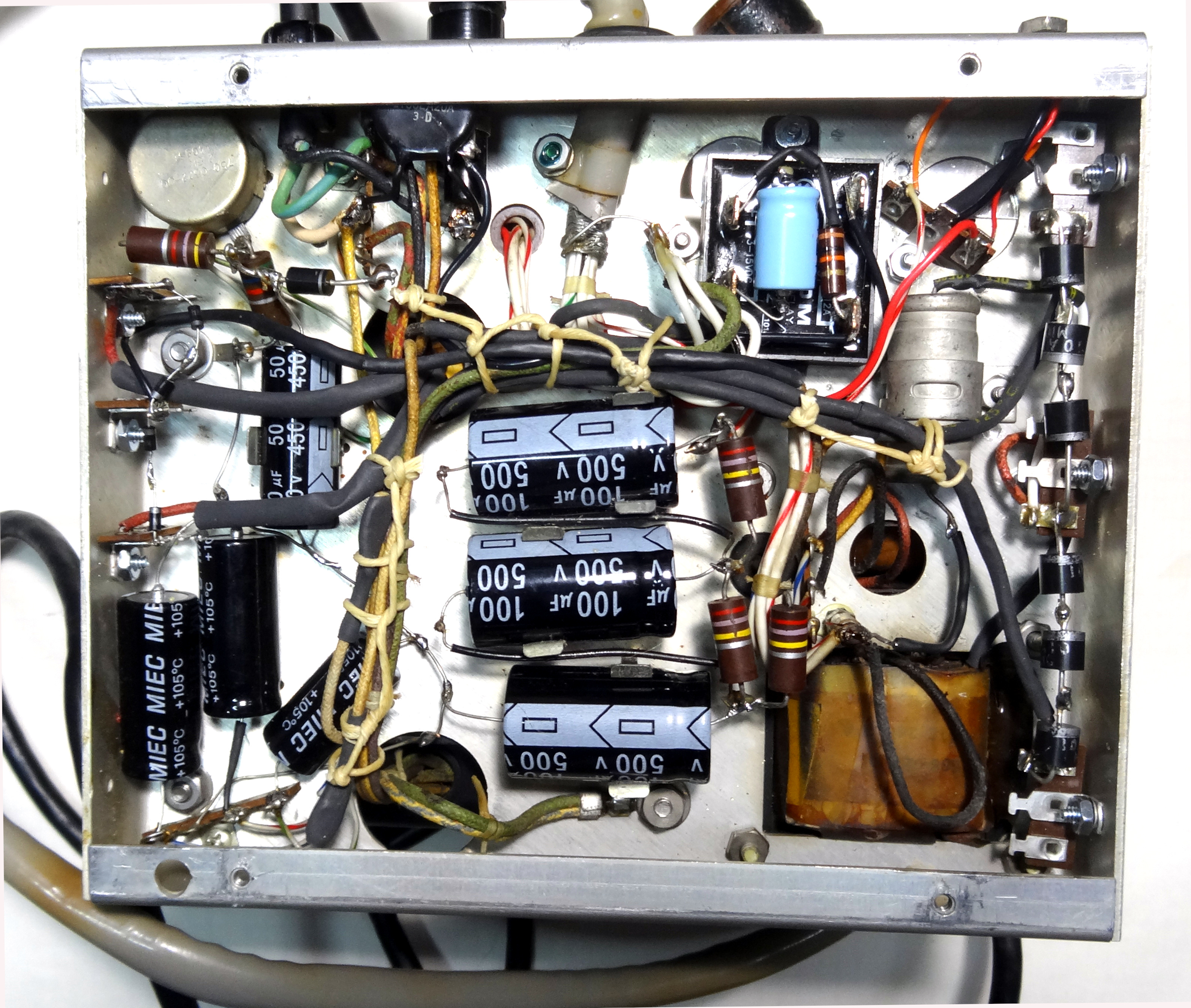 View showing the 516F-2 after modifications. Most of the original wiring harness ties were removed to allow for repositioning of cables and retied after changes were made.
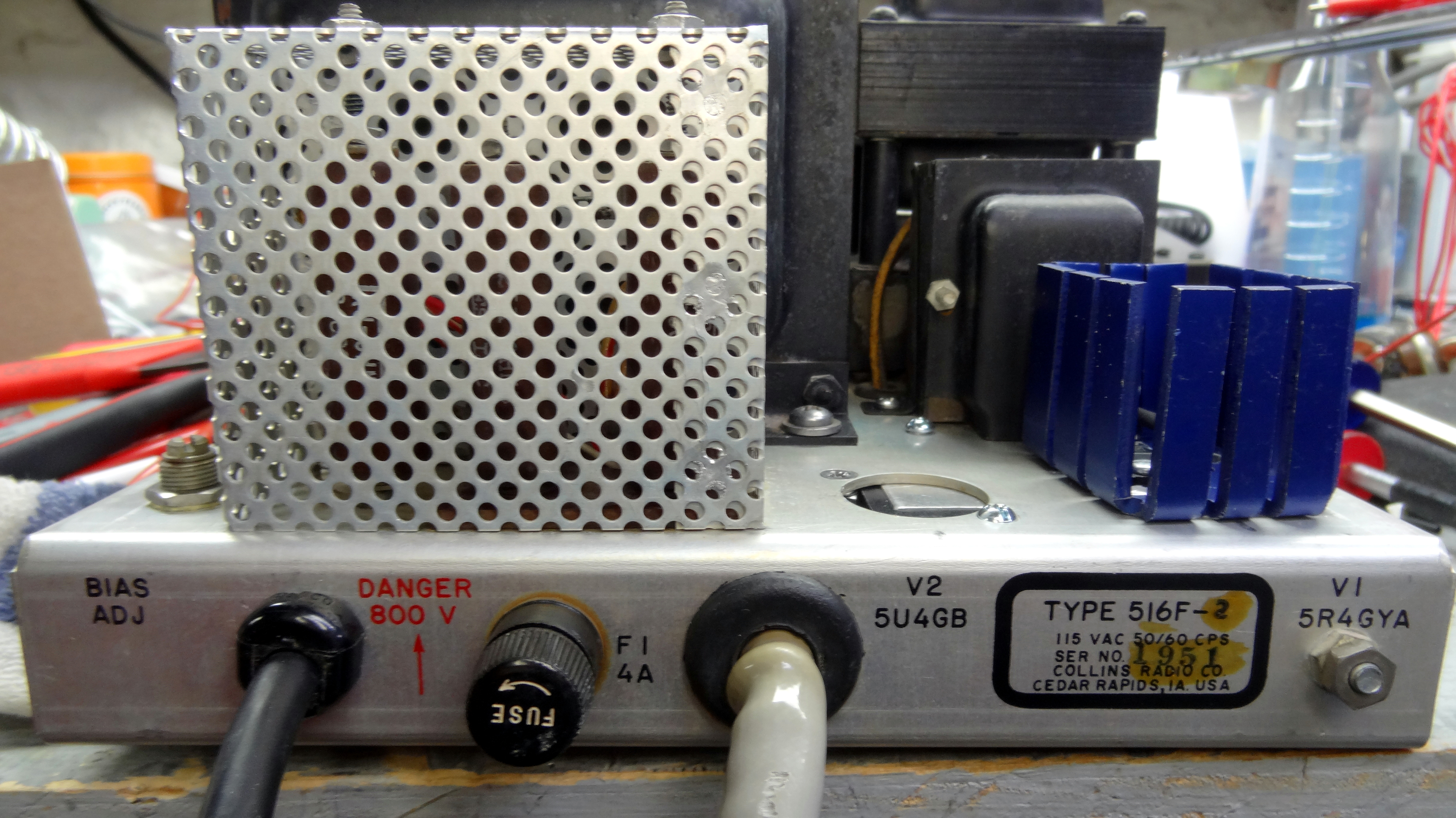 One method of mounting the heatsink and MOSFET. In this case the other components are mounted under the chassis.
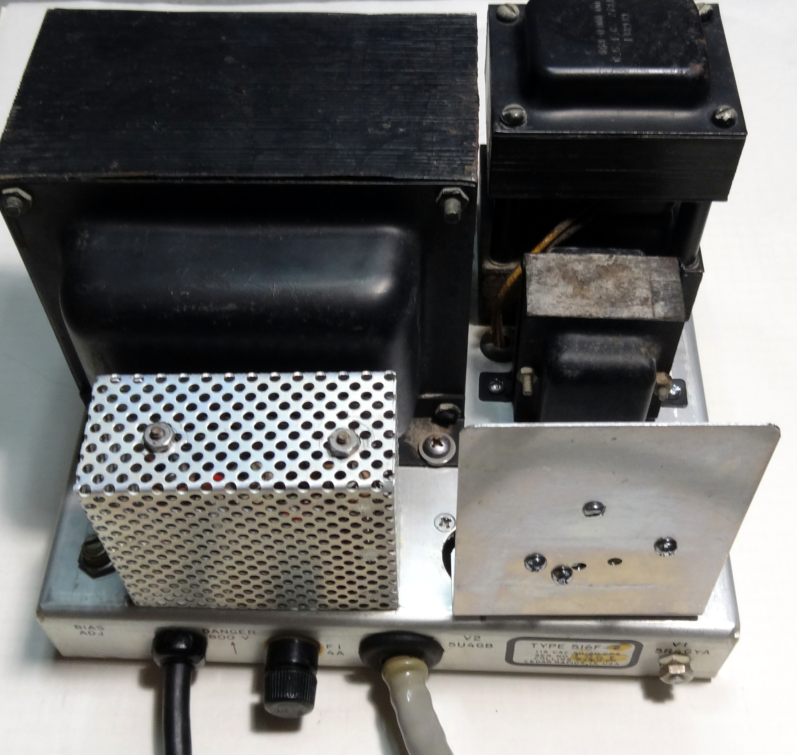 Another method mounting regulator and components on an aluminum plate. Plate is large enough that it protects a user from getting fingers on front side.
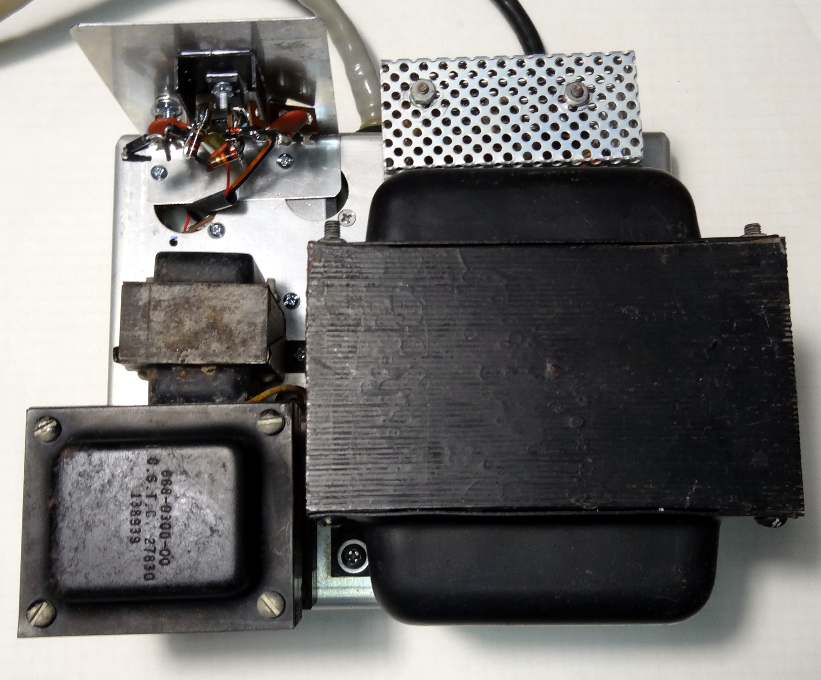 Top view of the 516F-2 show the back side of the regulator board.
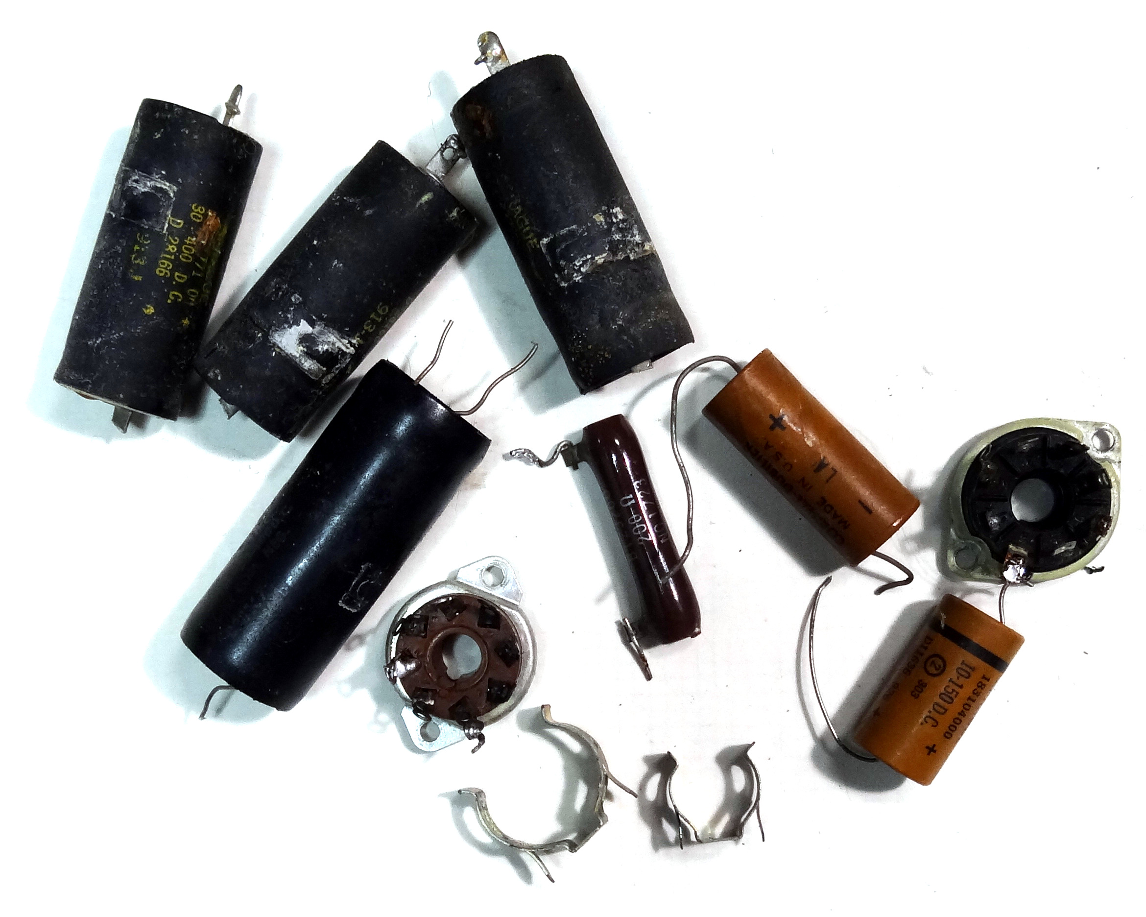 Parts removed from the supply during modification.
- First Schematic showing all of my modifications made to the 516F-2
- Later schematic showing minor changes.
- PDF schematic of original 516F-2 by KK5IM
- or download directly from his site
- Link to a good replacement for the high voltage choke resonating capacitor Also KE9PQ.com
Links to other WA3DSP Sites
© 2022 WA3DSP