Hallicrafters SX99 Restoration
Hallicrafters Radio History (from Wikipedia)
William J. Halligan founded his own radio manufacturing company in Chicago in late 1932. Prior to this, he had been involved in radio parts sales for some years but decided the time was right for a handcrafted amateur radio receiver - the company name being a combination of Halli(gan) and (hand)crafters. The new company was located at 417 State Street and immediately ran into patent difficulties when RCA decided to sue them for building radio sets without an RCA patent license. An opportunity came to purchase the concern of Silver-Marshall Inc. in 1933 and, with it, an RCA patent license as the most valuable asset.
In order to meet their financial obligations, Hallicrafters produced radios for other manufacturers until they were financially able to begin production of their own line of communications receivers, starting with the SX-9 'Super Skyrider', in late 1935.
By 1938, Hallicrafters was doing business in eighty-nine countries and manufactured the most popular sets in the USA. That year, the company began to produce radio transmitters. With the outbreak of World War II, the company prepared for wartime production, and was responsible for new designs and innovations for use by the U.S. troops; probably the best-known were the HT-4/BC-610 and related equipment used in the military SCR-299 communications package.
Production of Ham radio gear and other items was suspended until 1945. After the war, focus was again on consumer electronics, including radio phonographs, AM/FM receivers, clock radios and televisions.
The boom years for Hallicrafters were from 1945 to 1963, during which the company produced equipment considered by many to be superbly designed, including the famous S-38 receiver, which received a cosmetic "makeover" by industrial designer Raymond Loewy. In 1952 Hallicrafters' main plant in Chicago housed general offices and the factory and was a block long. In addition to the main plant was a 3-story building of 72,000 square feet (6,700 m2) two blocks away, a 1-story coil plant of 12,000 square feet (1,100 m2) on Chicago's north side, and 150,000 square feet (14,000 m2) of production and storage space in three other buildings within a five-mile radius of the main plant. The company employed 2,500 people.
During the Cold war era, the company took active participation in the Blue Streak (UK) and Atlas (U.S.) missile projects, helped to develop capability for many areas of electronic warfare and in missile field, including code translator data systems, ground support equipment, electronic countermeasures testing and antenna systems, infrared homing techniques, also company provided tactically deployed maintenance and technical support teams for mentioned missile systems, it supplied airborne target simulator system for Nike Zeus, electronic countermeasure systems for Douglas EB-66E and Boeing B-52 aircraft. Its R&D divisions (Manson Laboratories in Wilton, Connecticut, and Military Electronics Division in Chicago) developed penetration aids for intercontinental ballistic missiles and participated in various other classified programs. In the words of its advertising sloganry, the company supported żAmericażs defense umbrella.ż
In 1966 Halligan sold the company to the Northrop Corporation and Halligan family involvement ended. Northrop ran the company until the early 1970s, but by this time, fierce Japanese competition was putting pressure on the US domestic electronics market. Northrop sold the company name (but kept the factory, by then located in Rolling Meadows, a Chicago suburb) in 1975, bringing non-military electronics production to an end. The Hallicrafters plant became Northrop Corporation's Defense Systems Division.
The name and assets of Hallicrafters were traded over the following years, even though there were no products bearing the name. Since around 1988, the remaining assets and rights to the 'Hallicrafters' name and logos have been held by court-appointed trustees. (Note: one known 1980s product bearing the Hallicrafters name does exist - a 4-line plus intercom telephone.) Hallicrafters equipment remains in use by collectors and vintage amateur radio enthusiasts.
My SX99 Restoration Project
(Click any photo to see a larger view)
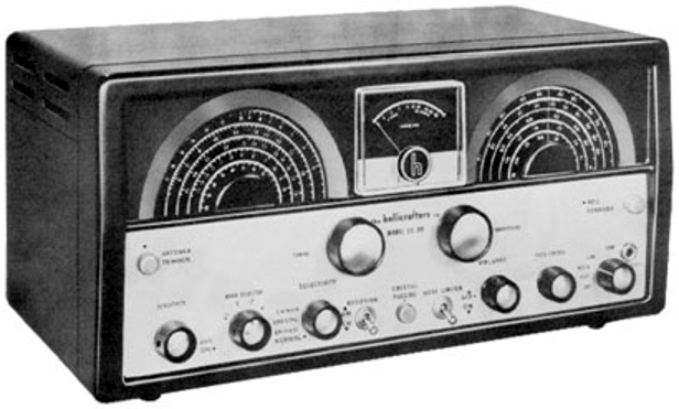
In summer 2020 I received an email from a former fellow employee of the Naval Air Development Center that he had a Hallicrafters SX99 that found in his fathers belonging. It was rather dirty, missing a band-switch knob and the line cord was cut off. I put it on the shelf for restoration and I finally got to it latter in the fall of 2020. The first thing I did was give it a bath. I use a special simple green designed for aircraft. I covered the IF can holes with painters tape and poured a mixture of Simple Green Extreme Aircraft and Precision Cleaner and water over the entire chassis. It cleans metal surfaces very well. Be careful of rubbing labelling on the front panel! Then it dries in the heat of the sun and inside for a week or two. The dial cords for both the main and band-spread tuning needed restringing which meant the front panel needed to be removed. I used a heavier dial cord than the original and it worked well.
The next order of business was replacing capacitors. I replaced all of the tubular capacitors in the radio and removed the original can electrolytic and covered the opening with a piece of aluminium. One thing you need to take into account for radios of this age is that electrolytic capacitors were physically much larger than they are today. The original filter electrolytic was a 30/10/10uf@450V can. In my final designed I used three 100uf@450 volt tubular electrolytics. Many older radios used marginal B+ filtering that resulted in a low level but audible hum in the output. Redesign of the power supply and using the large value capacitors resulted in imperceivable hum in the audio which would be great for headphone use. I replaced the old line cord with a three wire grounded plug, added a fuse and safety bypass caps on the line. I slowly applied power with a variac and the radio came to life.
I started checking voltages and they were higher than the design values most likely due to a higher line voltage than the radio was originally designed for. See voltage chart below. Radios were typically designed for a nominal 115VAC back then and today's line voltages are usually 120V or higher. Mine typically measures 121-122VAC. I was also not happy with the heat developed by the additional voltage, the power transformer heated considerably more than I thought it should. So a 2021 redesign of the power supply was in order. I added a 10H choke on top chassis where the can electrolytic had been. I also replaced the 5Y3 rectifier with diodes installed in a plug in to the original socket. I used the now unused 5Y3 5V winding to buck the primary thus giving close to 115VAC at my line voltage. This resulted in considerably lower B+ levels than the original design and everything worked as expected and ran much cooler. I never could understand why manufacturers pushed B+ levels on tubes. A 6K6 Audio output tube works just as well at 200VDC as it does at 250VDC and the life of the tube is extended. I also added a .1 ohm resistor in the filament line. This reduced the filament voltage from about 6.5VAC to 6.15 VAC as measured with a digital voltmeter. Again extending the life of the tubes. The final schematic changes are shown below.
DC Voltage Readings
| Condition | (A) Before 1.5K | (B) After 1.5K/900 | (C) After 12K |
|---|---|---|---|
| (1) Schematic values | 330 | 240 | 185 |
| (2) Actual Original Circuit @121VAC | 345 | 244 | 184 |
| (3) With diodes @121VAC | 389 | 272 | 207 |
| (4) With Choke and Diodes, 1.5K, @116VAC | 257 | 183 | 138 |
| (5) With Choke and Diodes, 1.5K, 5V buck, @121VAC | 256 | 183 | 138 |
| (6) With Choke and Diodes, 900 ohm, 5V Buck, @121VAC | 256 | 205 | 139 |
Note the after 1.5/900 and 12K are the values used by the radio. The first column is before the 1.5K or 900 ohm resistor.
Items 2-6 use three 100uf@450V capacitors in place of the original 30/10/10 Can Capacitor.
The result is an SX99 running at 205VDC vs. 244VDC and 139VDC vs. 184VDC with much better regulation and much lower ripple.
Filament voltage @121VAC with bucking was 6.5VAC. After .1 Ohm series resistor it was 6.12VAC.
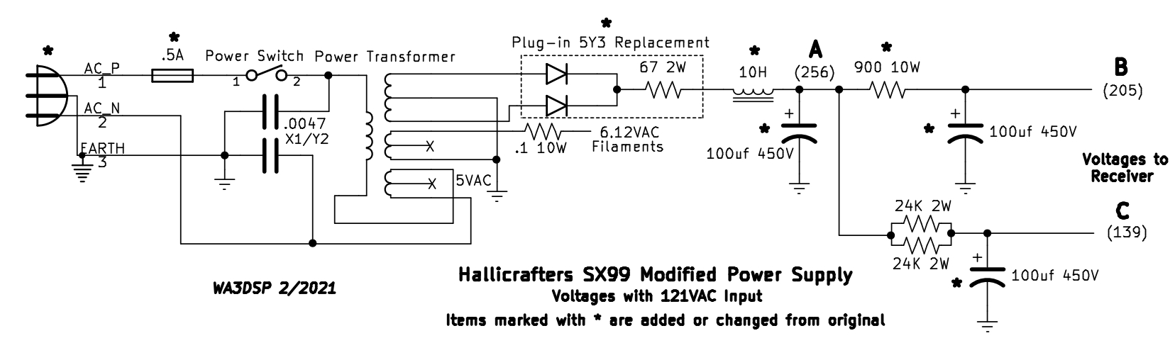 The SX99 Power Supply schematic showing the modifications made. Measurement points marked A,B,C.
 Photo showing under-chassis power supply section of SX99 with modifications in place. Fuse holder mounted inside rear chassis, AC line with three wire cord, 5V winding from 5Y3 used for primary bucking and safety bypass capacitors, Choke wiring through grommet, terminal strip added with three 100uf 450V electrolytics, 5Y3 socket rewired for diodes, Filament series resistor mounted on side panel at upper right.
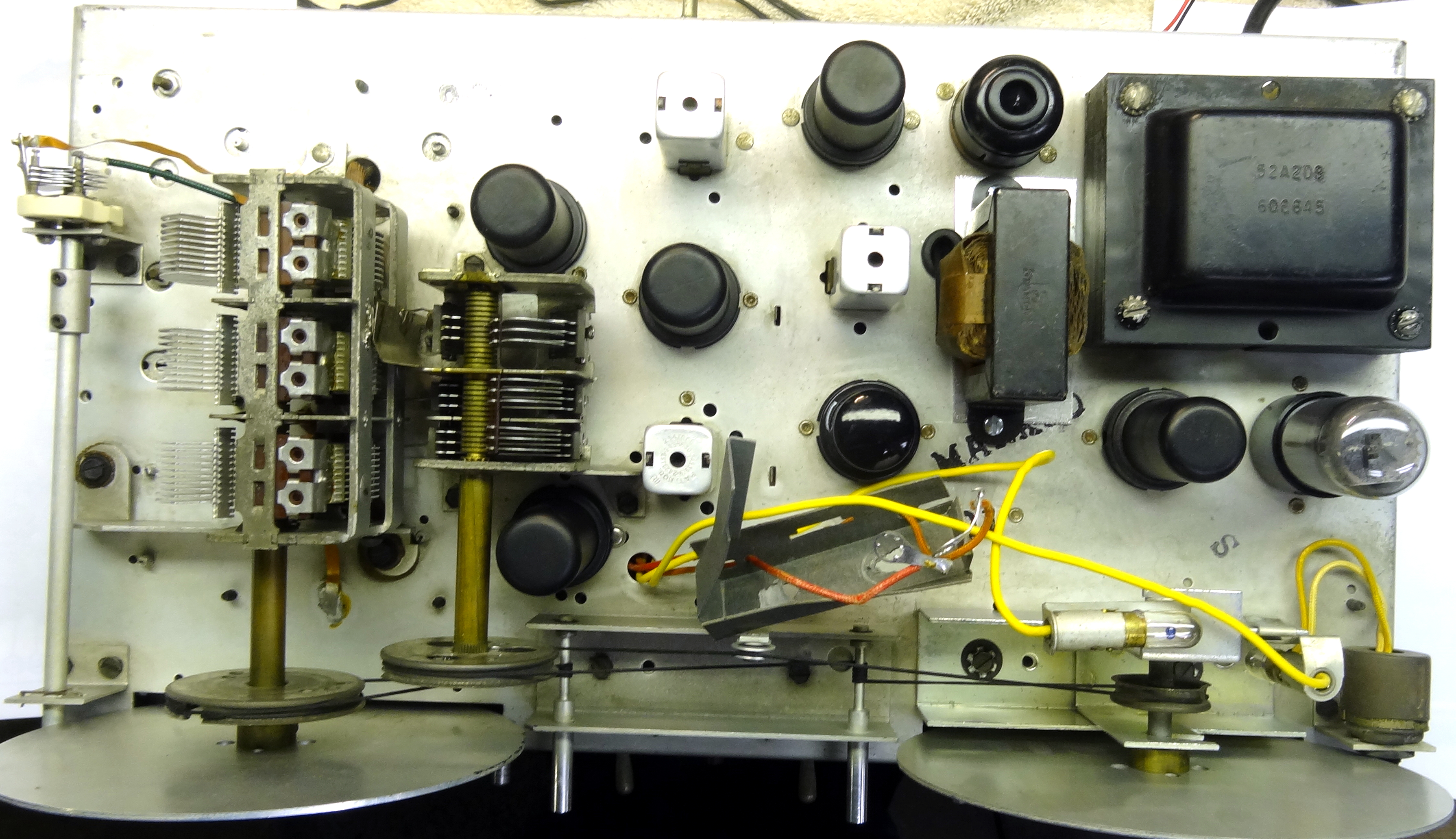 SX99 Top chassis with front panel removed. Dial cords restrung, Choke in place of Can electrolytic, Home-brew plug-in replacement for 5Y3.
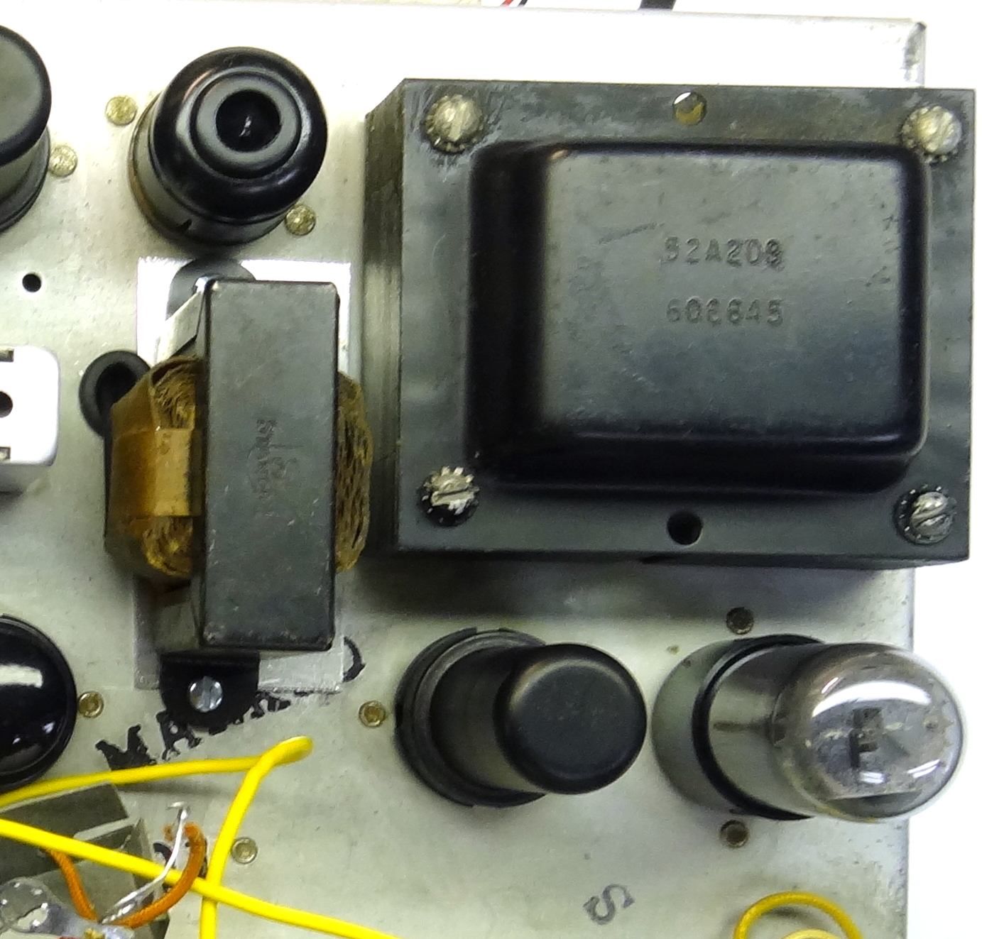 Close-up showing Choke placement and plug-in 5Y3 replacement.
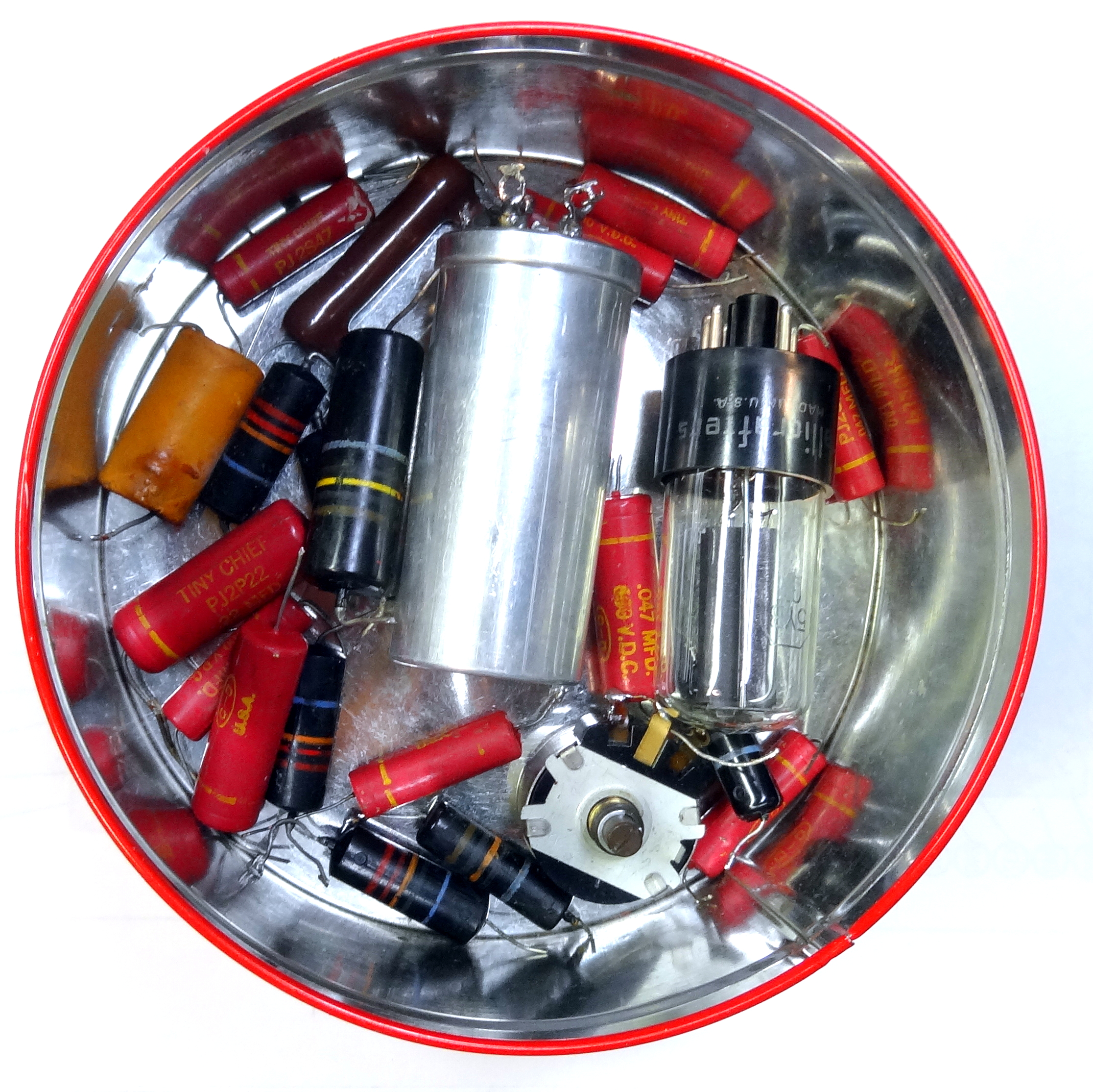 Photo showing the parts replaced during the restoration. All tubular capacitors, 5Y3 rectifier, S-meter zero pot, electrolytics. etc.
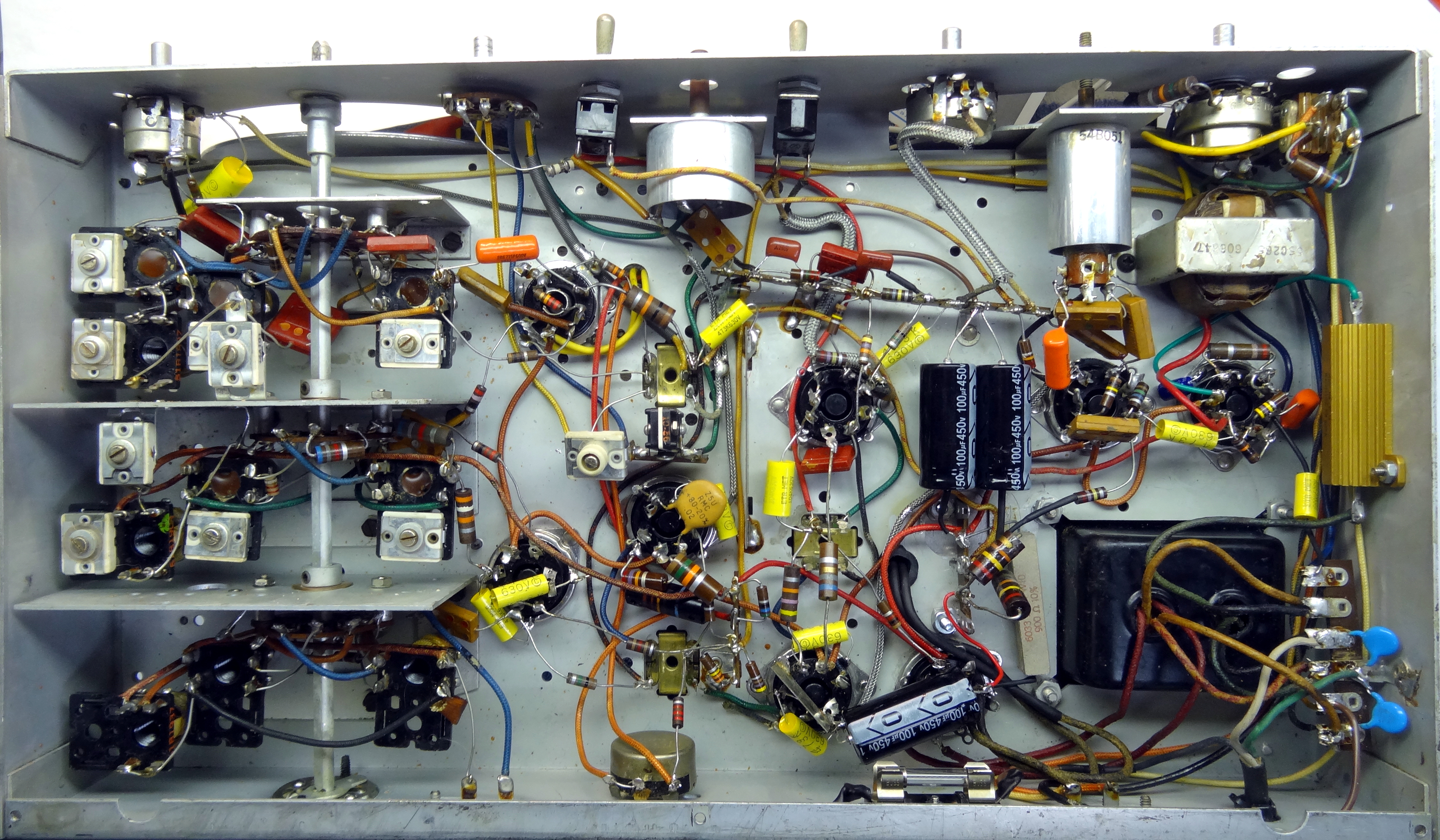 SX99 showing entire bottom chassis front panel removed. All tubular capacitors have been replaced, four electrolytics, Choke added, fuse added,
3 wire cord and safety bypass capacitors added, filament series resistor added, S-meter pot replaced.
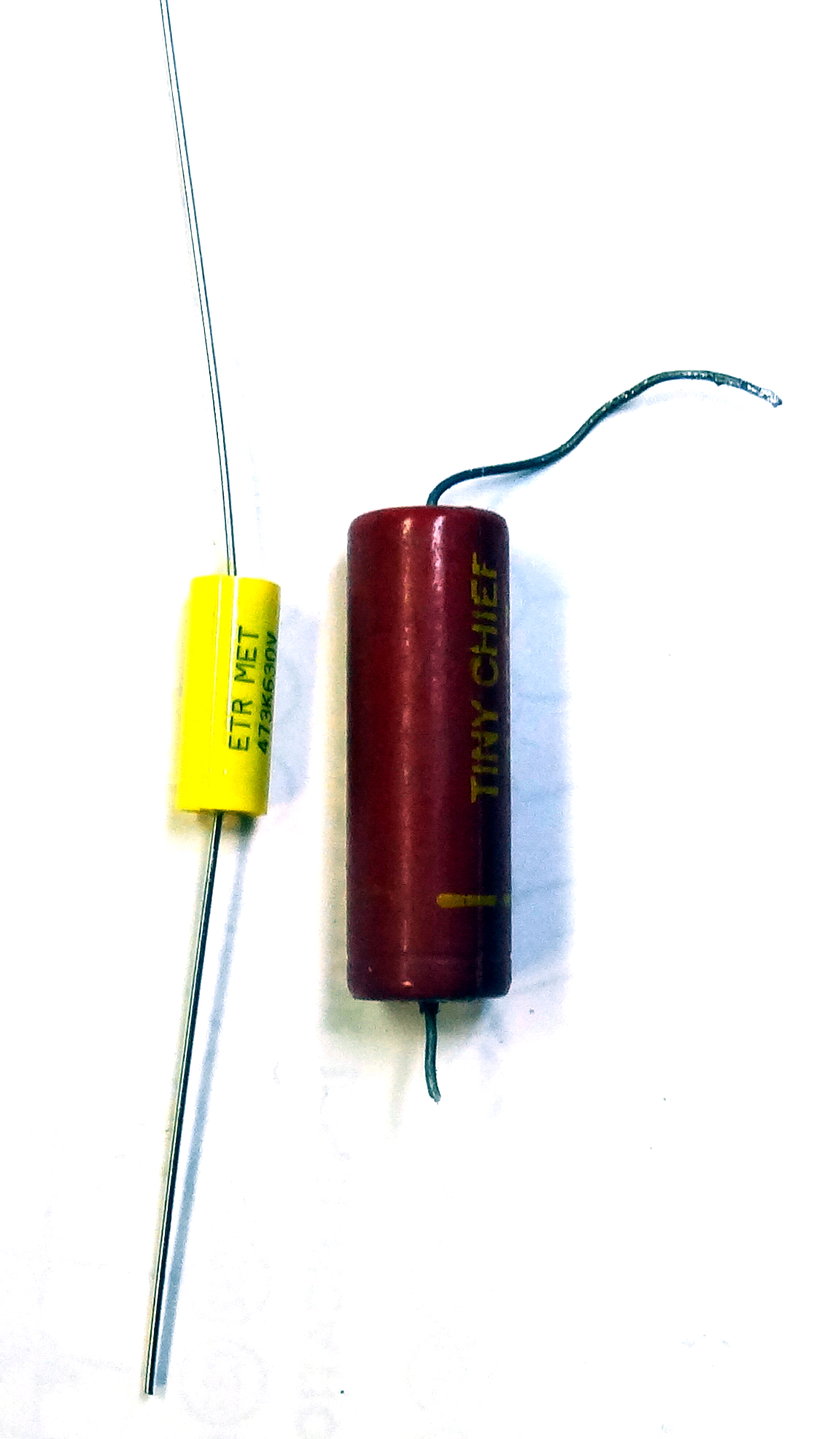 Photo showing difference in size of original tubular capacitor and modern replacement.
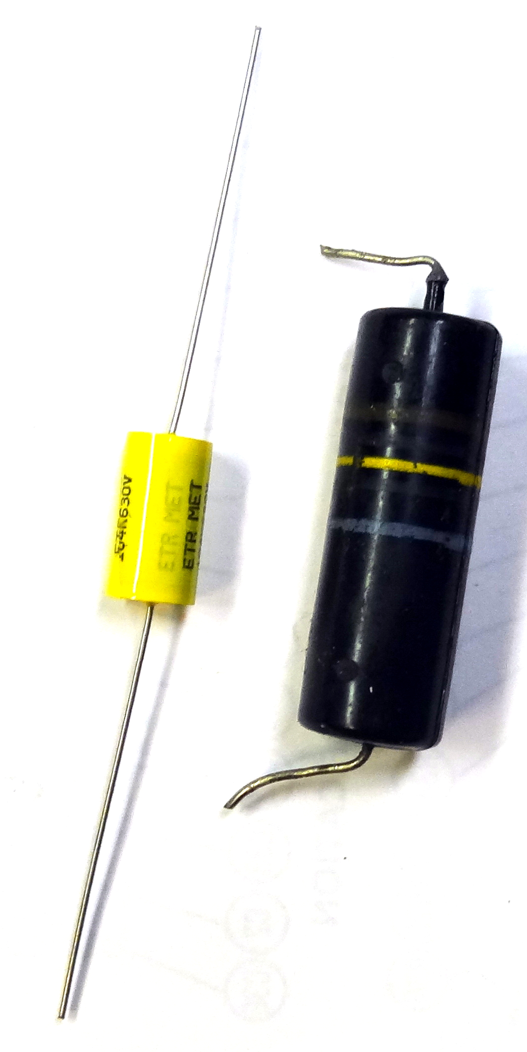 Photo showing difference in size of old tubular capacitor and modern replacement.
Because of the difference in size of the original and replacement capacitors they can often be mounted differently. Many are bypass capacitors and it is important to keep the inductance (length of leads) low. This was a little hard to do with the old large capacitors and as you can see in the photo the new ones are generally installed with the shortest possible path to a ground when they are used as bypass capacitors. When replacing capacitors there is no need to mount the ground end to the same point as the old capacitor as this would just increase the inductance. Ground them to the nearest good ground point.
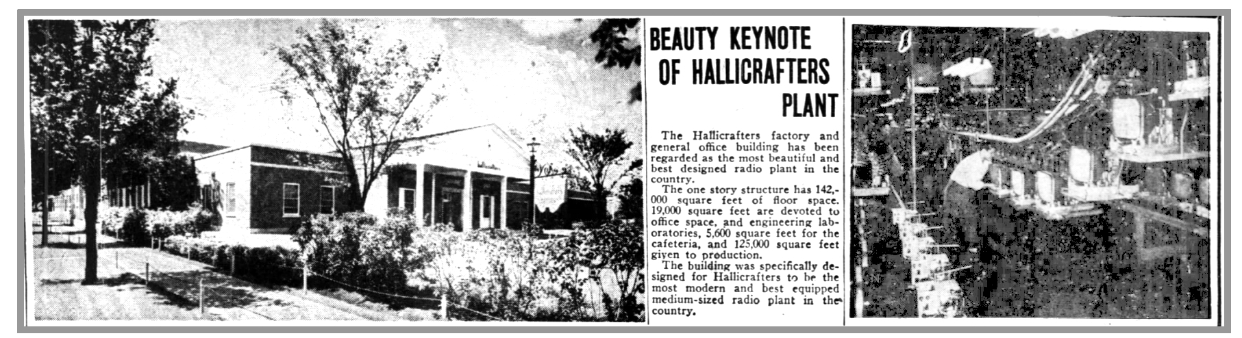 Former Hallicrafter Factory, Chicago, IL
Schematics and Operating Manuals
Hallicrafter Radio Links
- Wikipedia Hallicrafter Radio
- Made in Chicago Museum
- Hallicrafters Virtual Museum
- Jim's Hallicrafters Museum
- WWII Film of Hallicrafters factory
This page last updated 2/18/2021
© 2021 - WA3DSP