The WA3DSP Raspberry Pi
IRLP Node in Cape May, NJ
My second Pi IRLP node is located at my home in Cape May, NJ. It is a simplex node on 147.44 with an 88.5 PL. Here are some photos and a description of the installation.
(Click any photo to see a larger view)
 Comet CX333 antenna mounted on roof.
 A Channel Master roof mount with 18 inch soffit offset was used.
My Cape May, NJ installation was constructed much like my first Pi node. The exception is the method of powering the Pi and IRLP boards. A three terminal regulator is used to derive the 5V from a 12V input. Power is applied directly to the Pi board by soldering to the input of the 3.3V regulator. This allows powering of the Pi from the same 12V power source as the transceiver. It is also a much cleaner and better regulated source than the commonly used micro USB power supplies. Additional LED's were installed on the front panel to mimic all of the IRLP boards six LED's. The Pi board Link activity and power are also displayed. Unlike my first node box this node does not use a USB extender making the layout a little neater.
The antenna is a Comet CX333 tri-band 144/220/440 which I had laying around in my barn. The radials were missing so I contacted Comet and ordered a replacement set. I have another 144/440 antenna mounted on my chimney and I wanted to mount this antenna towards the back of the house. Unfortunately there was a soffit overhang in the way but a Channel Master mount with an 18 inch offset solved the problem. I mounted two treated 2X4's on the siding and the mount to the 2x4's. It made a solid installation which holds a five foot mast and CX333 very well.
The node radio is an Alinco DR-135 and a Jetstream JTPS14 Power Supply. IRLP interfaces very nicely to the Alinco radios with there DB9 data connectors.
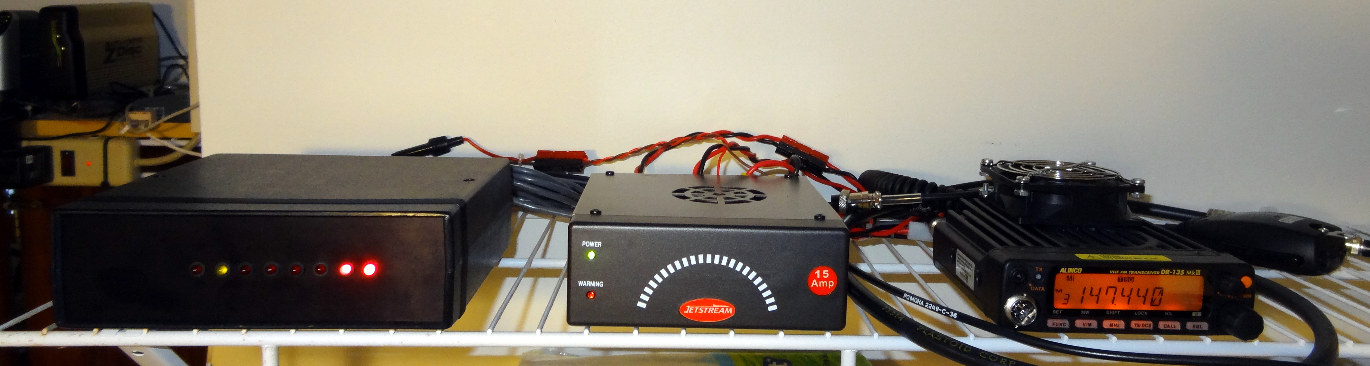 Pi box, Jetstream power supply, and Alinco 2 meter transceiver with cooling fan installed. I used a 24 volt fan running on the 12 volt supply which is very quiet and keeps the Alinco cool through long transmissions.
Since IRLP duty cycles can be very high especially on a busy reflector a cooling fan is usually a must. You do not have to move much air over the heatsink chassis of the ALinco to keep it cool. I used a small 24 volt muffin fan running on the 12V supply. It gives just enough air to keep the chassis cool and is very quiet.
As long as you have connectors cables are easy to make and you can save a lot of money doing it yourself. Some of the prices I see for custom cables are ridiculously high. The cable with a DB9 female (IRLP end) to a DB9 male (Alinco end) is wired like this:
|
If you purchased the Pi modified version of the IRLP board Pin 2 (PTT) and 3 (Aux1) are jumpered at the board and the connector jumpering is not needed. Shielded cable is preferred.
While it is very easy to interface to the Alinco radio you can use other radios. You just need a source of receive audio preferably taken just before the volume control but after any de-emphasis. Also PTT and TX audio which in most cases would need to be voltage dropped if fed directly into the mic input. COS is a received signal indication which usually comes from a PL or squelch circuit. The polarity and level for COS is configurable on the IRLP board.
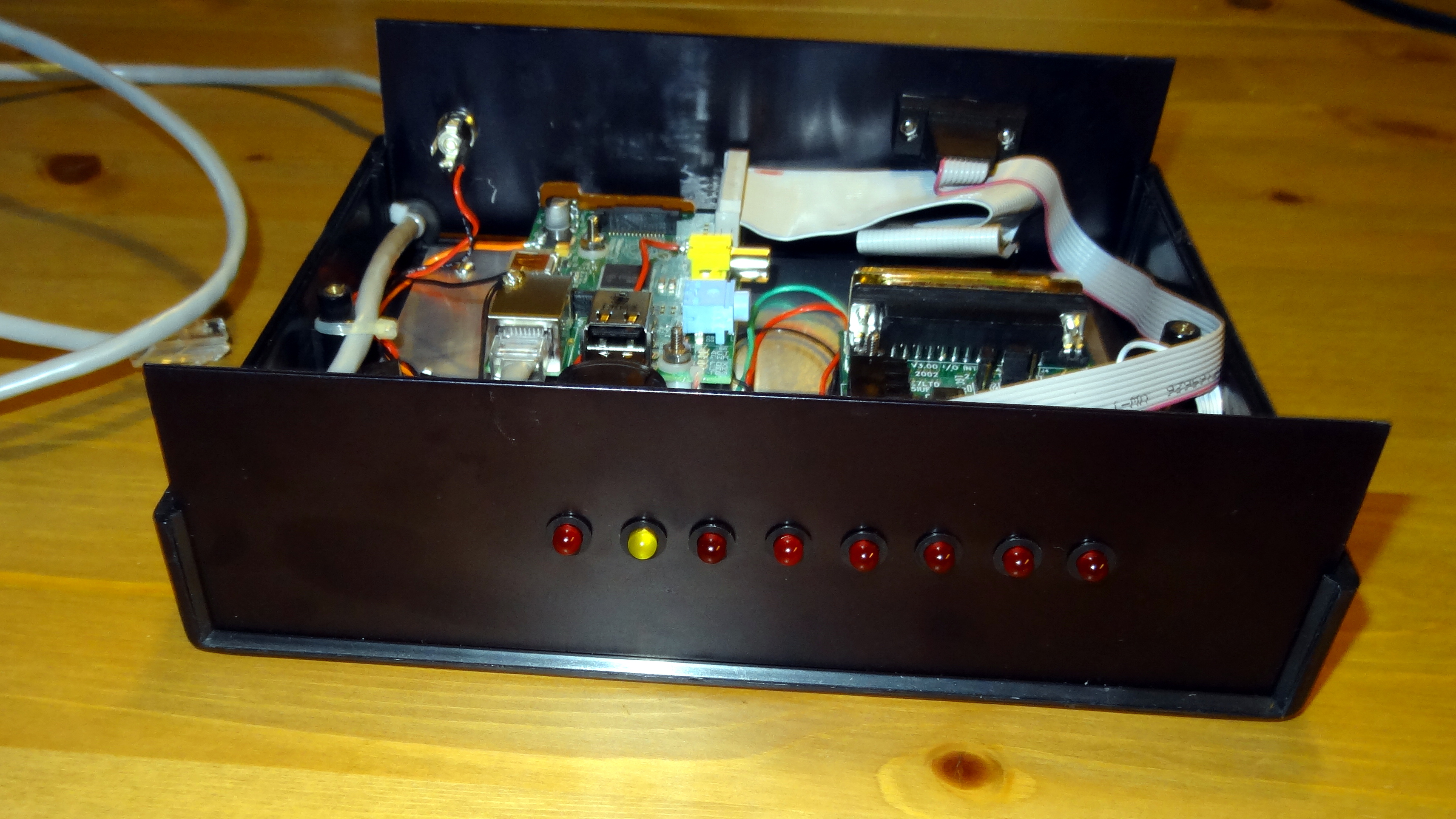 Front panel of IRLP interface. LED's are from left, PTT, COS, DTMF, Aux1, aux2, aux3, Link Activity, and Power.
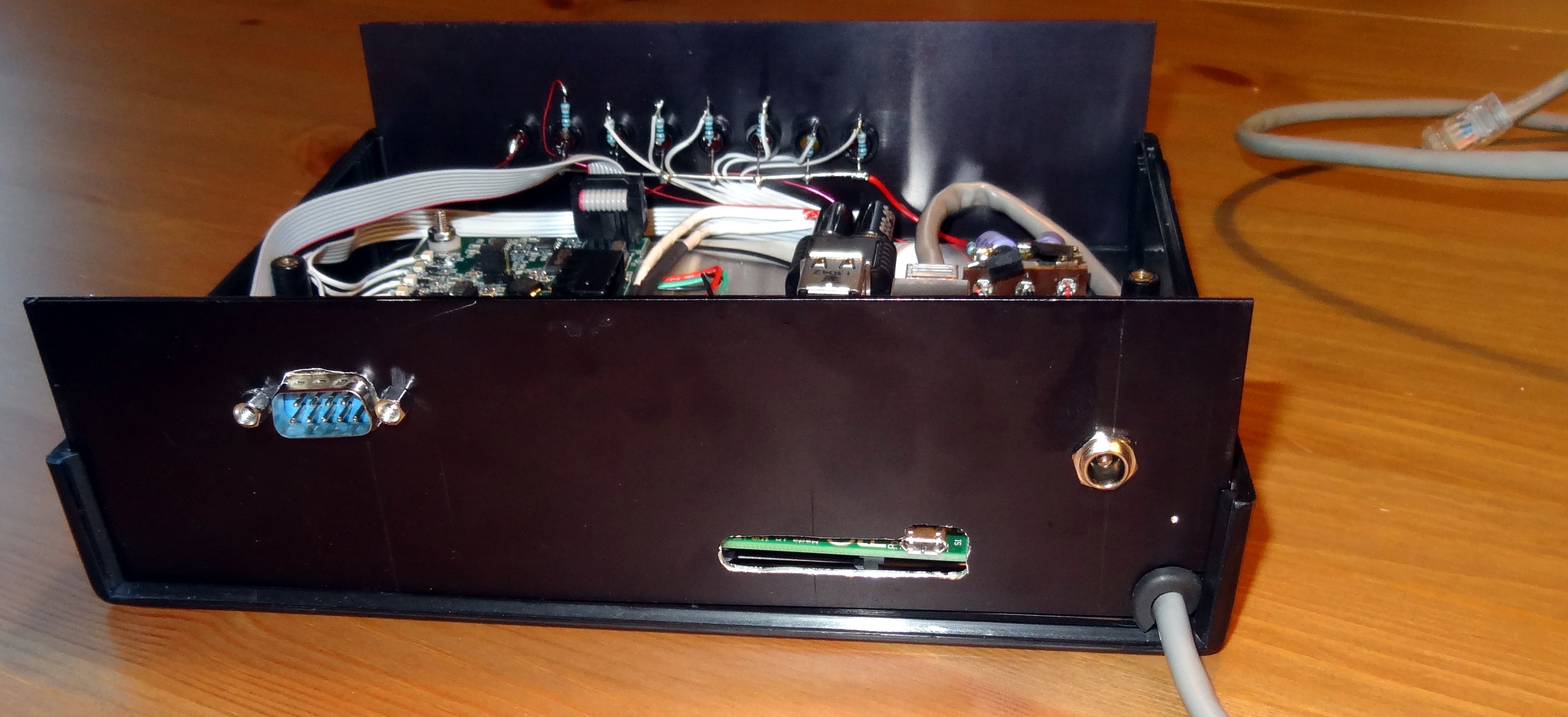 Read panel of IRLP interface. DB9 radio interface at left, SD card slot and micro USB, Power connector and Ethernet connection at right.
 View showing the power entry, regulator and Raspberry Pi.
 Another angle of the same view.
In this node I used an LM7805 three terminal regulator to supply the 5 volts. Input voltage can be from 7 to 30 volts but I would generally keep it below 15 volts for dissipation reasons. There is a series diode on the positive input at the rear power connector. The aluminum base serves as a heatsink. The 5V connection to the Raspberry Pi is soldered to the input of the 3.3V regulator. Connections are also made to the Pi for 3.3V to the front panel LED's and for the link LED. The connection for the power LED comes from the 5 volt terminal strip. Front panel LED's are pulled DOWN by the Pi and IRLP boards through 330 ohm resistors. The positive side of the LED's goes to 3.3 volts from the Pi board. The power LED indicator is fed from the 5V supply through a 330 ohm resistor.
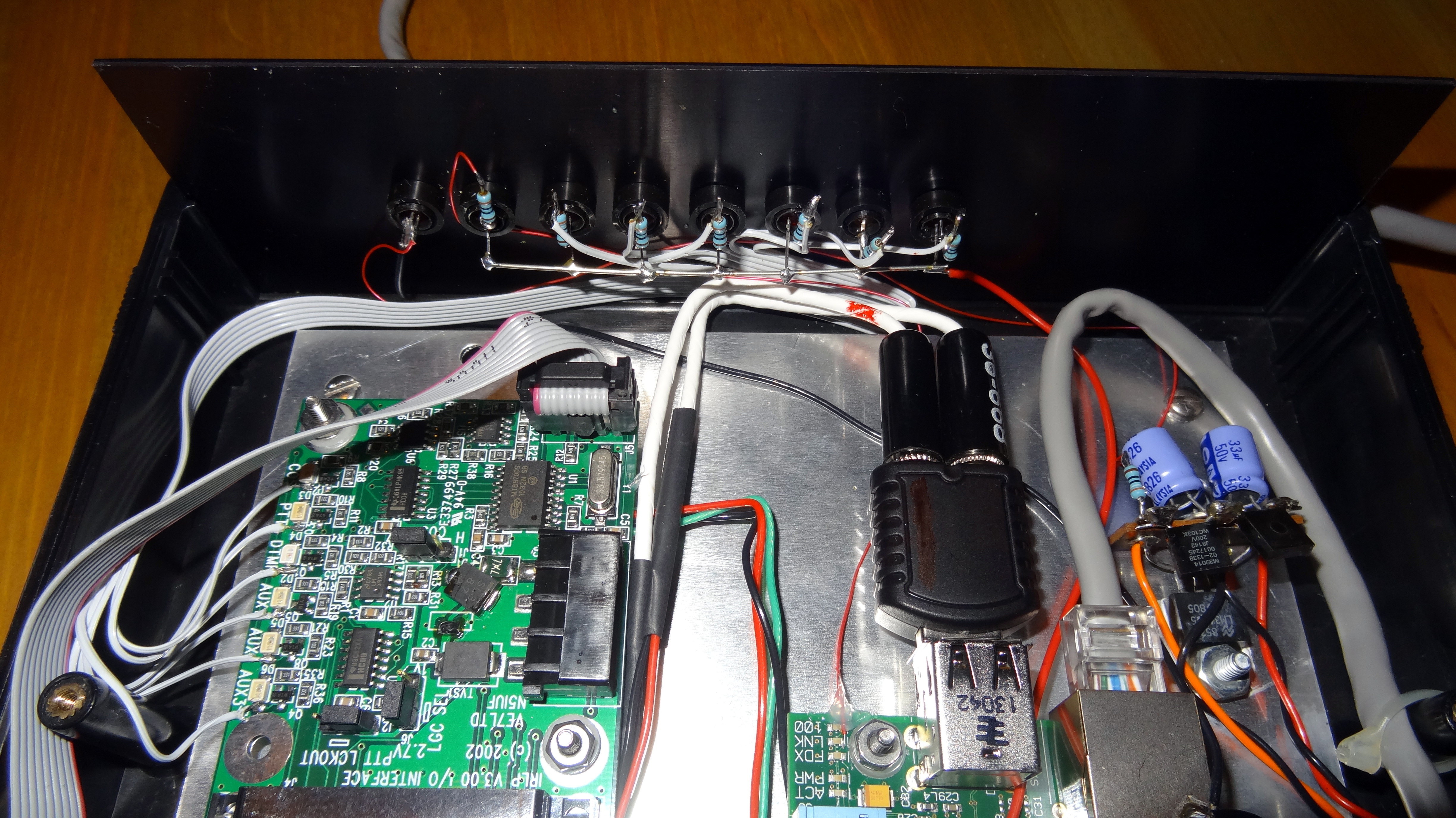 View showing LED connections to the IRLP board and front panel LED's
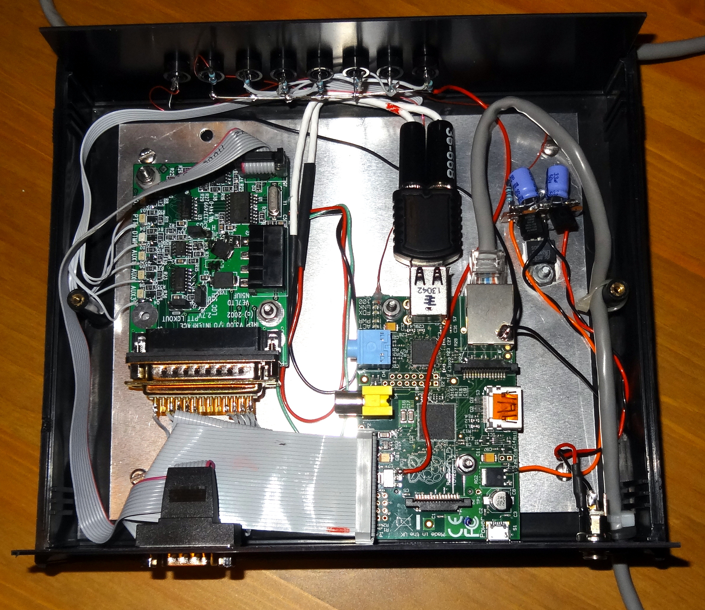 The entire inside of the IRLP interface box.
Cloning a Pi node
This node was cloned from my node 8444 located in Richboro, PA. If you want to clone a Pi node, saving all of your scripts and configuration, and create a NEW node on another public IP address it is rather easy to do assuming you have some Linux experience. I created a new install script from the Debian install new script that Dave created. I won't make it available for download but if you are interested drop me an email and I will send it to you. I modified the script because I wanted to make an indentical node to the first one I created but receive a new node number and PGP key. Running this script it takes about 10 minutes to create a new node. The simplified procedure is to copy the image of the original WORKING node to a new SD card. Install the new SD card in your new hardware. Then bring down the old node and test the new hardware using the old node number. Get everything set the way you want it using the complete new system including the radio. Then save your audio settings. You then take the node to its new location and make sure you have the correct internet settings. If the network is differnet you need to make sure you change these settings before you leave the original location. Unless you know the new networks LAN IP address range it might be a good idea to put it back in DHCP mode and set static up at the new location. In my case I had set up both locations with the same net topography. IP address and the gateway need to be set correctly. Once you have static IP setup at the new location you can run the script and get a new node number. The new node will operate exactly like the old node. You won't have to reload anything. A more detailed description of this is in the script comments.
I would be glad to answer any questions or comments. Send them to my email address at qrz.com. 73 Doug, WA3DSP
This page last updated 7/7/2013
© 2013 - WA3DSP