Amateur Radio Station
Microphone Switch Box
Description
Like many amateur radio operators I have a number of rigs at my operating position. I also have my favourite microphone, a D104, with a source follower FET amplifier to match the high impedance element to modern low impedance 600 ohm inputs. Having six D104's to service all of my operating position HF rigs would not be very practical so I designed a switch box to allow the one microphone to be used with up to six rigs of any impedance input. I have also incorporated CW key switching capability.
Since most all modern rigs use powered microphones I switch the power as well. In my case it powers the FET in my D104. For older rigs that do not have microphone power I included an 8 volt regulator powered from an external 12 volt source.
(Click any photo in this article to see a larger view)
Construction Considerations
The purpose of this article is to give the reader ideas. You do not have to follow exact construction details and you can modify the design in any way you desire. Perhaps you only need two or three switch positions or you don't need to switch CW. Feel free to be inventive and change things. That's what amateur radio construction is all about.
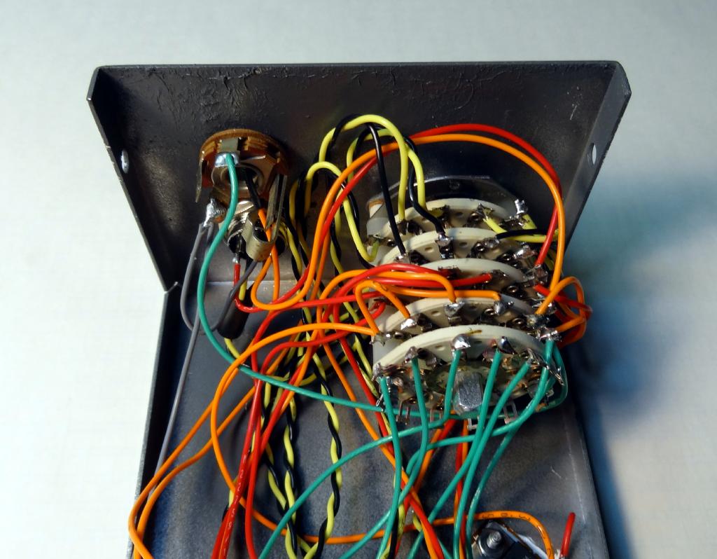
I used a 5 wafer, 5 pole, 6 position rotary switch. This switches BOTH sides of the microphone, hot and ground, PTT, 8VDC, and CW keying but you could greatly simplify this if you depending on what you need to switch and how many rigs you want to switch to. I felt it was a good idea to switch both sides of the microphone connection to eliminate potential ground loop problems. Note that the microphone ground and ground are the separate connections. If they are not separate connections on a particular rig they are connected together at the rig end of the connector.
Another consideration is how to wire the microphone connectors. I use standard 8 pin round connectors and since I have mostly Kenwood wired rigs I decided to keep everything as Kenwood standard for those connectors. I made adapter cables for my older rigs and my Icom IC7000 which uses an RJ45 type connector. You may decide you want to use Icom round connector wiring or a completely different connector. Whatever you use you will need a bunch of connectors. Everything is done with male chassis mount and female cable mount connectors.
Although not covered in this project there is another method that could be used to simplify switching. If you were to use multiple FET source followers from the microphone output to the various rigs and if you were able to connect the PTT lines in parallel you could eliminate virtually all of the switching. If you were to attempt that method you need to be careful about mixing PTT voltage levels. Some older rigs have higher PTT voltages and relay coil kickback that could cause damage to modern solid-state rigs. I prefer to individually switch the signals as I did in this project.
Getting the Parts Together

Whether you follow this construction as shown or make your own modifications you still need to secure the required parts. Shown in this photo is the minibox with holes drilled and finish painted. All of the major parts for the assembly are also shown. To make construction easier the wiring is soldered to the connectors before they are installed.
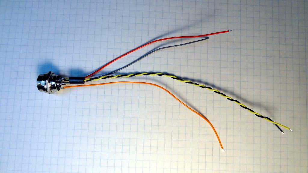 Photo showing the connector wiring. The ferrite bead is over the twisted pair microphone wires.
This was added as a precaution against RFI.
The wiring is all point to point. I use all Teflon wiring for my projects but any hookup type wire of about 22 gauge would work. You should use different colors for the different signals. Within the switch box I used twisted yellow and black for the microphone hot and ground, red for PTT, orange for +8VDC, and gray for ground. The Kenwood standard for the connections used is:
- Pin 1 - Mic
- Pin 2 - PTT
- Pin 5 - + 8VDC
- Pin 7 - Mic ground
- Pin 8 - ground.
For other microphone and rig connection standards see this web page
The following photos show interior wiring which follows the schematic.
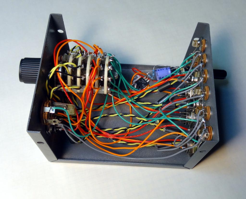
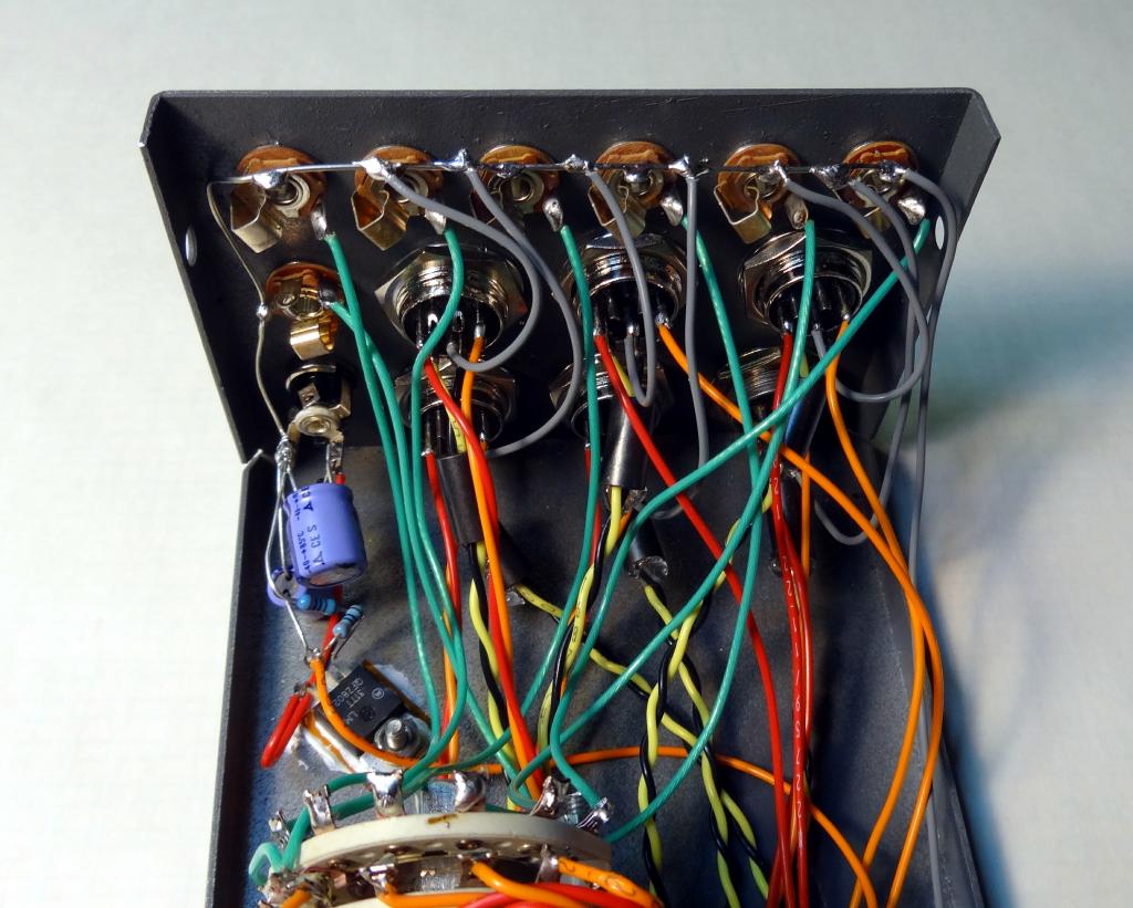
 This photo
shows a rear panel view with the six microphone connectors at the upper right. Cables are made between these connectors and the various rigs. Below are six mini-jacks
which are the CW connections to the rigs. On the left top is a 12V coaxial type connector for the 12VDC input. Left center is a rear panel
Key connection.
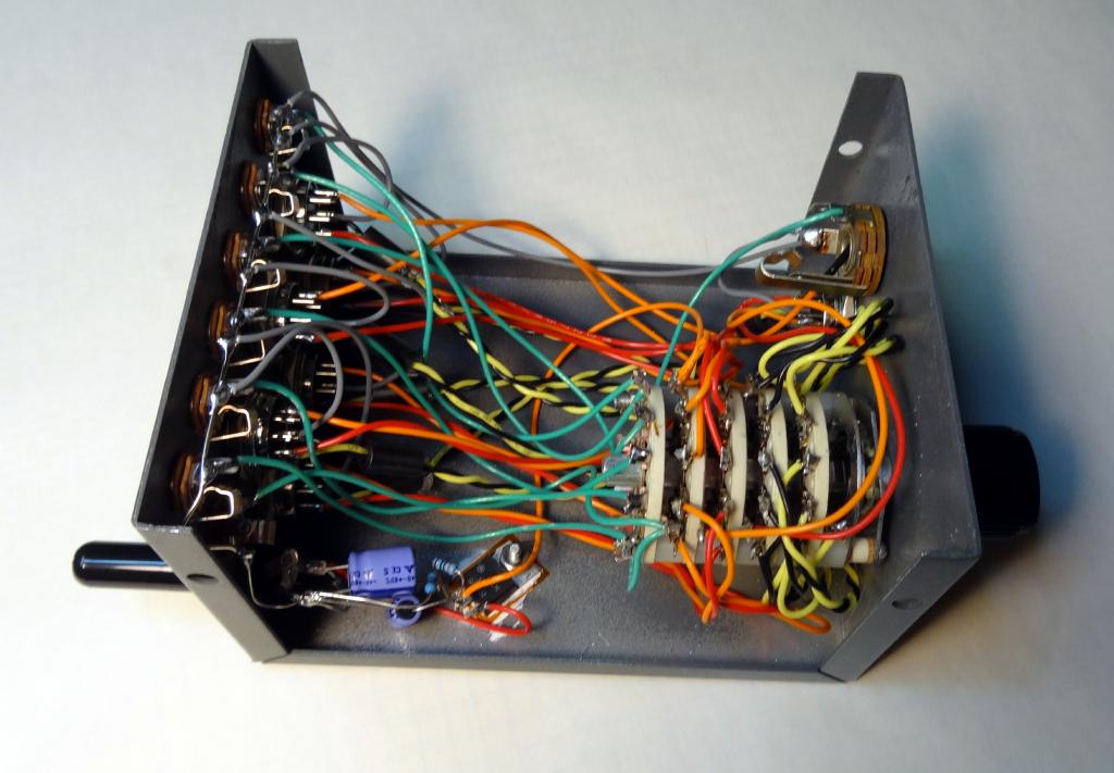
This photo
shows a rear panel view with the six microphone connectors at the upper right. Cables are made between these connectors and the various rigs. Below are six mini-jacks
which are the CW connections to the rigs. On the left top is a 12V coaxial type connector for the 12VDC input. Left center is a rear panel
Key connection.
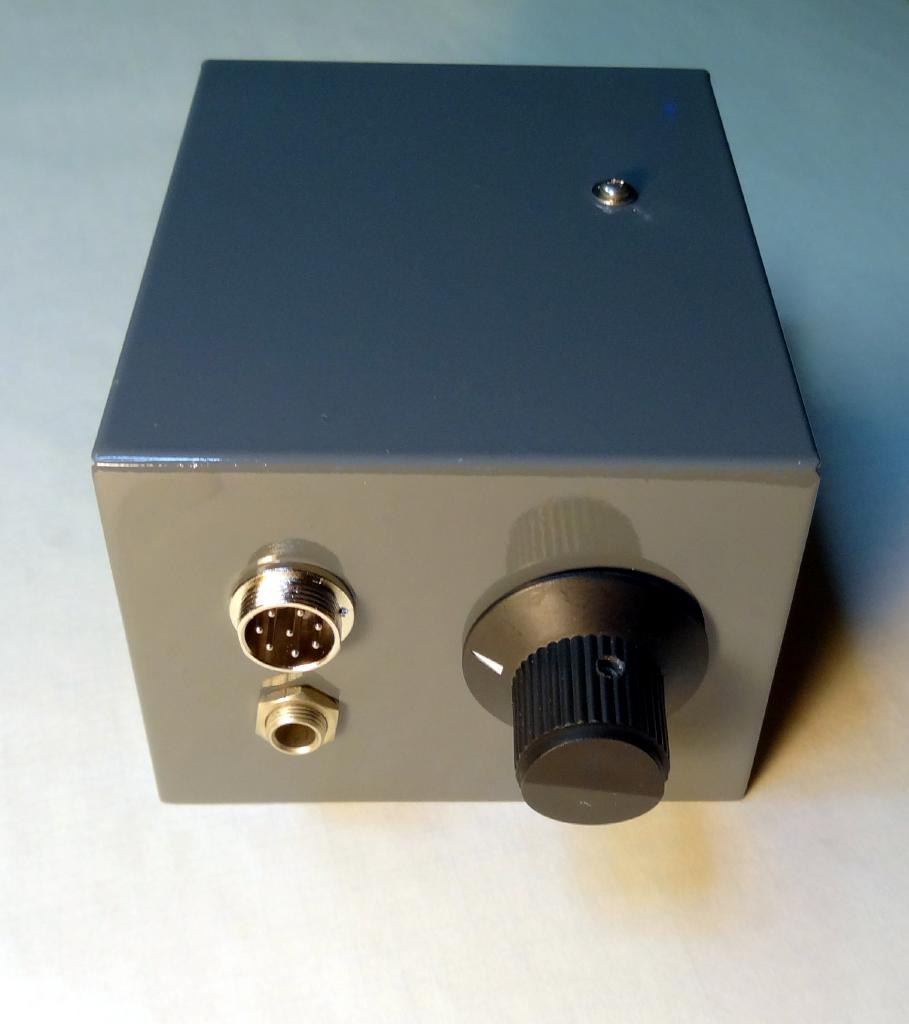
Front panel view, six position selection switch, Microphone input, and 1/4 inch CW key jack.Schematic
Microphone Switch Box Schematic
Parts List
The hardest part to get in this project is the rotary switch. I constructed a 5 pole 6 position switch from my junk box but keep in mind that this can be any number of positions two or greater depending on how many total rigs you want to switch. If you don't want to switch the CW keying then a 4 pole switch would be fine. If you also don't need to switch power 3 poles would suffice. More poles and/or positions then you need is not a problem as you just would not use what you don't need. I referenced a few places where rotary switches can be found below. Google 'rotary switches' for more possible options.
- Mic Connectors - Universal Radio / MCM
- Rotary Switch - Altech Electronics / Surplus Shed / Old Jock Radio
- 1/4" / 1/8" Jacks / Regulator / Resistors / Capacitors - Common parts - Radio Shack etc.
- Ferrite Sleeves - Surplus Sales
- Aluminium Chassis (4"x5"x3" minibox) - Amazon / Allied Radio / Bud info
I built my switch box entirely from my junk box and since some of the items may be obsolete substitution will be required. Hopefully the above references will help you to gather parts for your project. There are many other sources for parts including hamfests, ham friends, and the Internet.
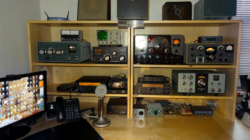 My upstairs shack showing the six HF rigs. Top shelf - SB200, LA1000, Johnson Ranger, Collins KWM2A. Middle shelf - Kenwood TS-590,
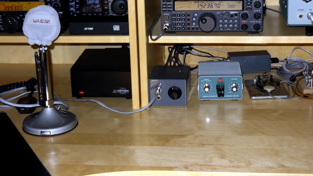
Icom IC7000 and LDG tuner, Kenwood TS-570, Heath HW101. Bottom shelf right side - microphone switch box, Keyer and various keys. SDR receiver and
sound interface.
My upstairs shack showing the six HF rigs. Top shelf - SB200, LA1000, Johnson Ranger, Collins KWM2A. Middle shelf - Kenwood TS-590,
Icom IC7000 and LDG tuner, Kenwood TS-570, Heath HW101. Bottom shelf right side - microphone switch box, Keyer and various keys. SDR receiver and
sound interface.Final Thoughts
I mentioned that I use the ubiquitous Astatic D104 microphone with all of my HF rigs. This microphone is no longer manufactured but so many were sold that they are plentiful in the amateur radio community. They use a crystal or ceramic element that has an extremely high impedance. Element loading of less than one megohm begins to be a problem and since most all HF rigs manufactured in the last 30 years have a 600 ohm microphone input impedance you cannot just connect a D104 to your rig. There are various ways to interface the D104 including a simple series resistor but in my opinion the best way to do it is use a source follower FET circuit. When doing this the FET gate is connected directly to the element and a gate leak resistor of 5-10 megohms is used resulting in very light loading on the element. The FET low impedance source then drives the input to the rig. If you have a D104 or a microphone like it and would like to build this FET source follower here is a link to the schematic. This is built on a small piece of perfboard and installed in the base of the microphone.
This was a fun project and with the combination of microphone and antenna switching I can use any of six different HF radios within seconds. This greatly reduces clutter and is a very worthwhile addition to the the shack. There are commercial microphone switch boxes like this MFJ 2 Rig/2 Mic box for $119. If you have a well stocked junk box you could certainly build a box like this with much more capability for considerably less than the commercial versions. Even if you had to buy all the parts new it would cost less and you would have the satisfaction of building it yourself. Happy building and I would be glad to answer any questions.
My email is good at QRZ. 73, Doug, WA3DSP
Visit my Amateur Radio web page at www.crompton.com/hamradio
This page last updated 2/2/2014
© 2014 - WA3DSP