A Simplified USB
Sound FOB Modification
Introduction
There are numerous USB sound FOB modification methods shown on various web pages on the Internet. My goal here was to make it as simple as possible. There are only two tricky connections for COS and PTT and with magnification they should be easy for most hams. While the RPi2 and BBB will eventually have GPIO capability for Allstar COS and PTT I really think it is much cleaner to just modify a FOB. Either way you have to build some kind of interface and with the BBB or RPi2 you risk the danger of damaging the board. FOB's are cheap, about $3-$5 and less than $3 in large quantities (10 for $2.40 each, 100 for $2.25 each). Some of the modifications out there do much more surgery on the FOB than is needed. These FOBS are delicate and can be damaged by messing with them beyond what you really need to do. You do NOT need to remove connectors! This project shows just 5 connections to the FOB, six if you have an extra ground lead.
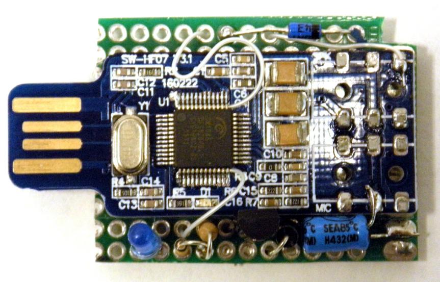
Modifying the board
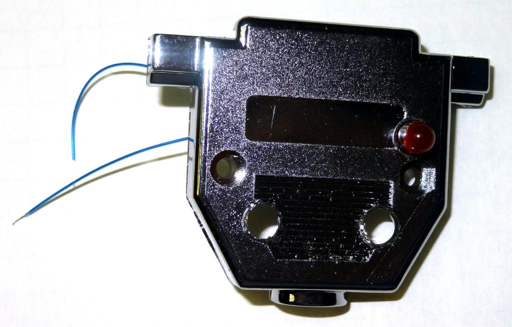
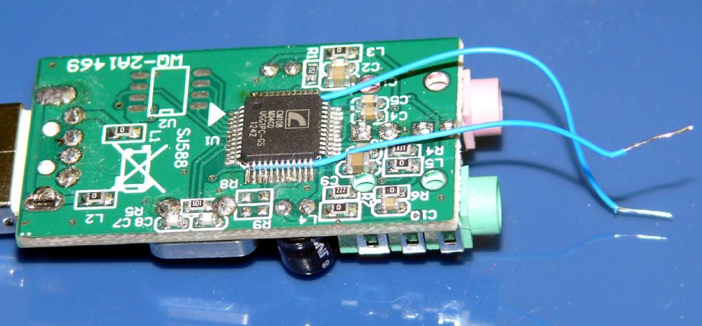
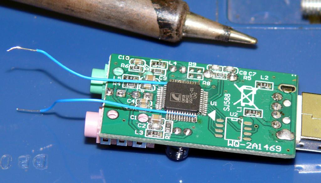
We start out by removing the board from its case. It practically falls out. The case and buttons can be discarded. It is nothing more than plastic and does not serve as any shielding. The case has to be removed anyway to allow plugging two or more FOBS into the RPi2 USB ports. Once removed two wires are soldered to the chip, one for COS and the other for PTT. #30 wire-wrap wire was used about three inches long. Tin both ends but don't leave an excessive amount of solder. Use magnification and a small tip iron and tack the leads onto the pins as shown in the photo. Clean the iron's tip and just wet it with a little solder. The is a tack process no additional solder is needed. Position the bare wire up against the pin on the outside away from the other pins and just touch the iron while holding the wire steady. It only takes a fraction of a second. FOBS are cheap so order several and use one to experiment if you are not sure of yourself in doing this. It is not that hard. Get up the courage and do it!
This is the ONLY mod you need to make to the board!
Once the wires are tacked on carefully position them as shown and use clear silicone sealant to secure the wire to the board so it will not pull off. Silicone sealant is available in small toothpaste size tubes from a home store and is very handy around the shack. It dries in a few hours.
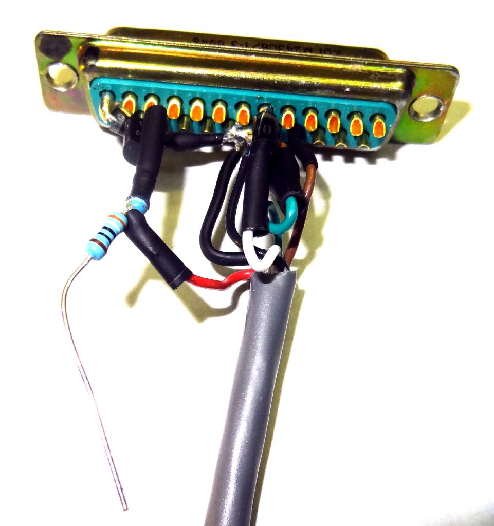
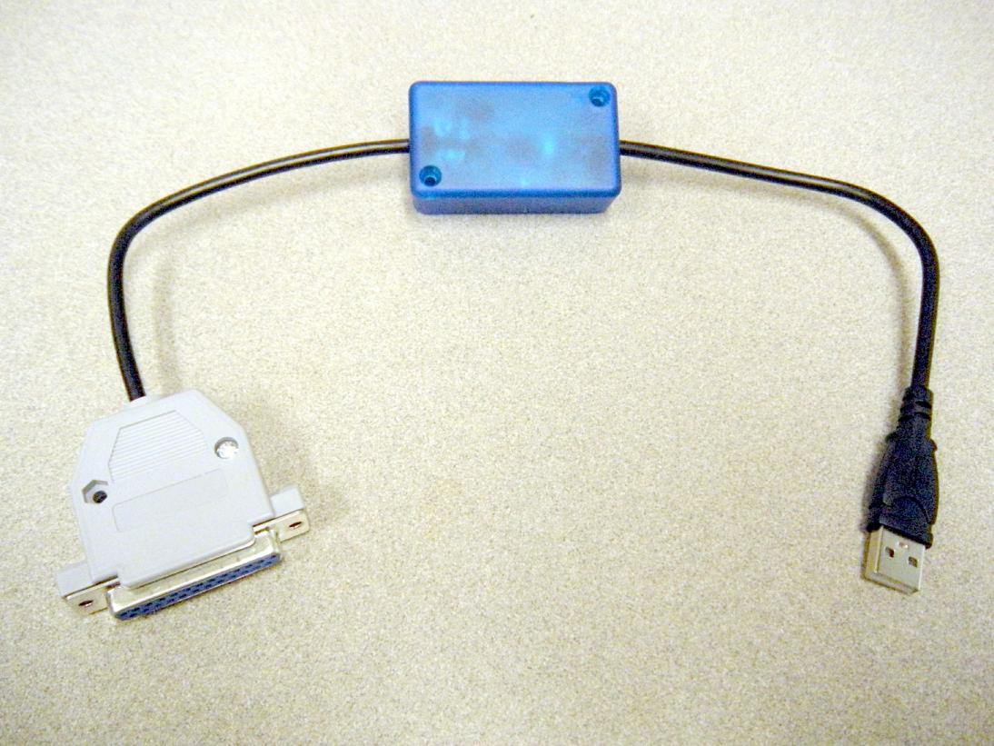
Now prepare a cable to go to the DB25. It needs to be at least 4 conductor shielded. In my example I had 5 conductor shielded so I used the extra lead as an additional ground. A good choice for cable if you don't have any acceptable cable laying around is an old USB cable. They are at least four conductor shielded cables. Cable length should be as short as possible. You will be using another cable with a DB25 male connected to this cable with your radio connector at the other end. This makes it totally compatible with switching between a DMK-URI and the modified FOB. I generally standardize on the individual wire colors shown here but you will not always have the same colors so you will have to make sure you write down the colors and definitions you use so you get it right when you connect the other end. The photo shows the locations to make the connection on the FOB. The wire-wrap COS and PTT leads are soldered to the cable leads and heat shrink is placed over them. Be careful when using a heat gun neat the FOB. Do NOT apply any excessive heat to the board. Put a shield between the wire and the board. DB25 pin numbering is shown on the schematic link below. I found that 1 inch heat shrink will fit over the board nicely if you want to enclose the FOB. I would not shrink it but if you must be careful with the heat. You could cut holes for the LED's.
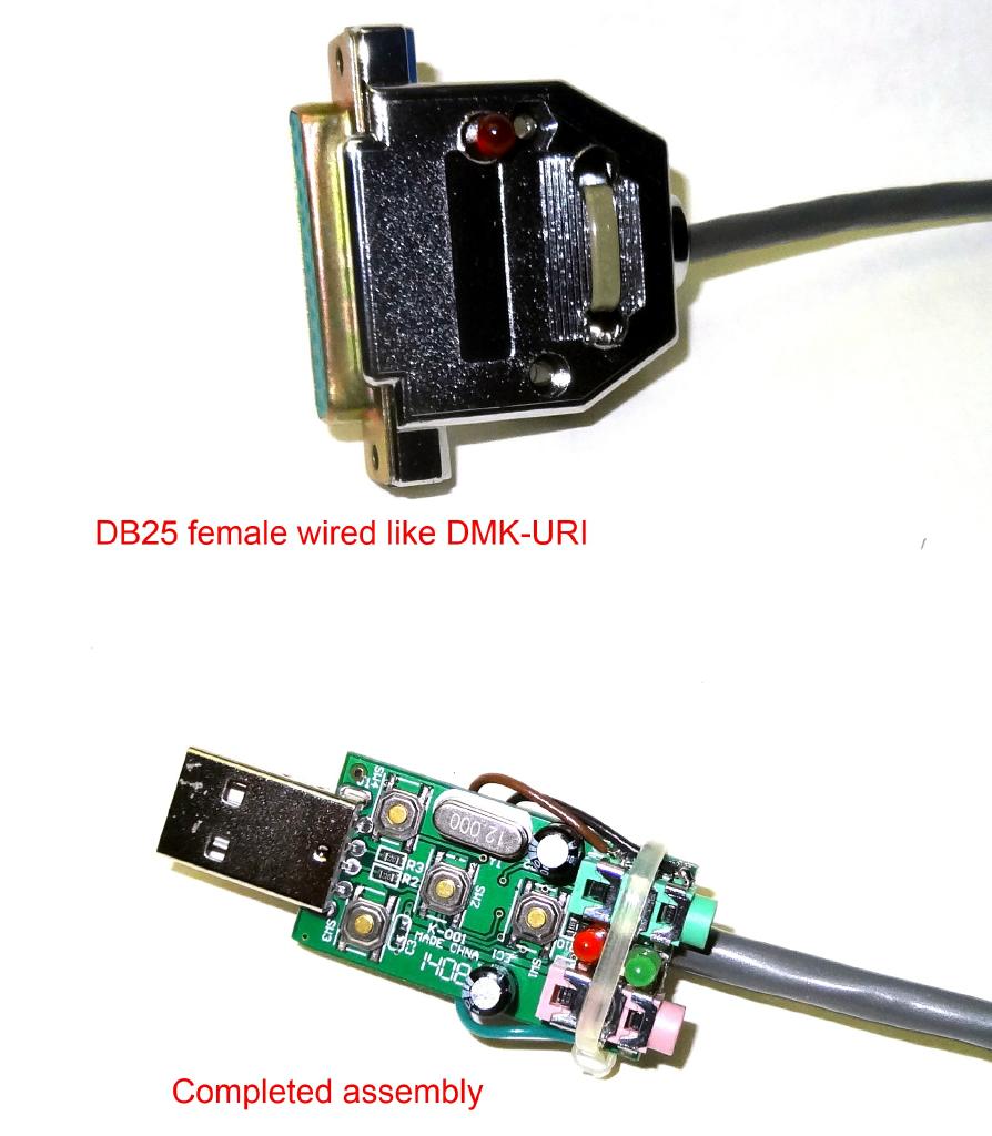
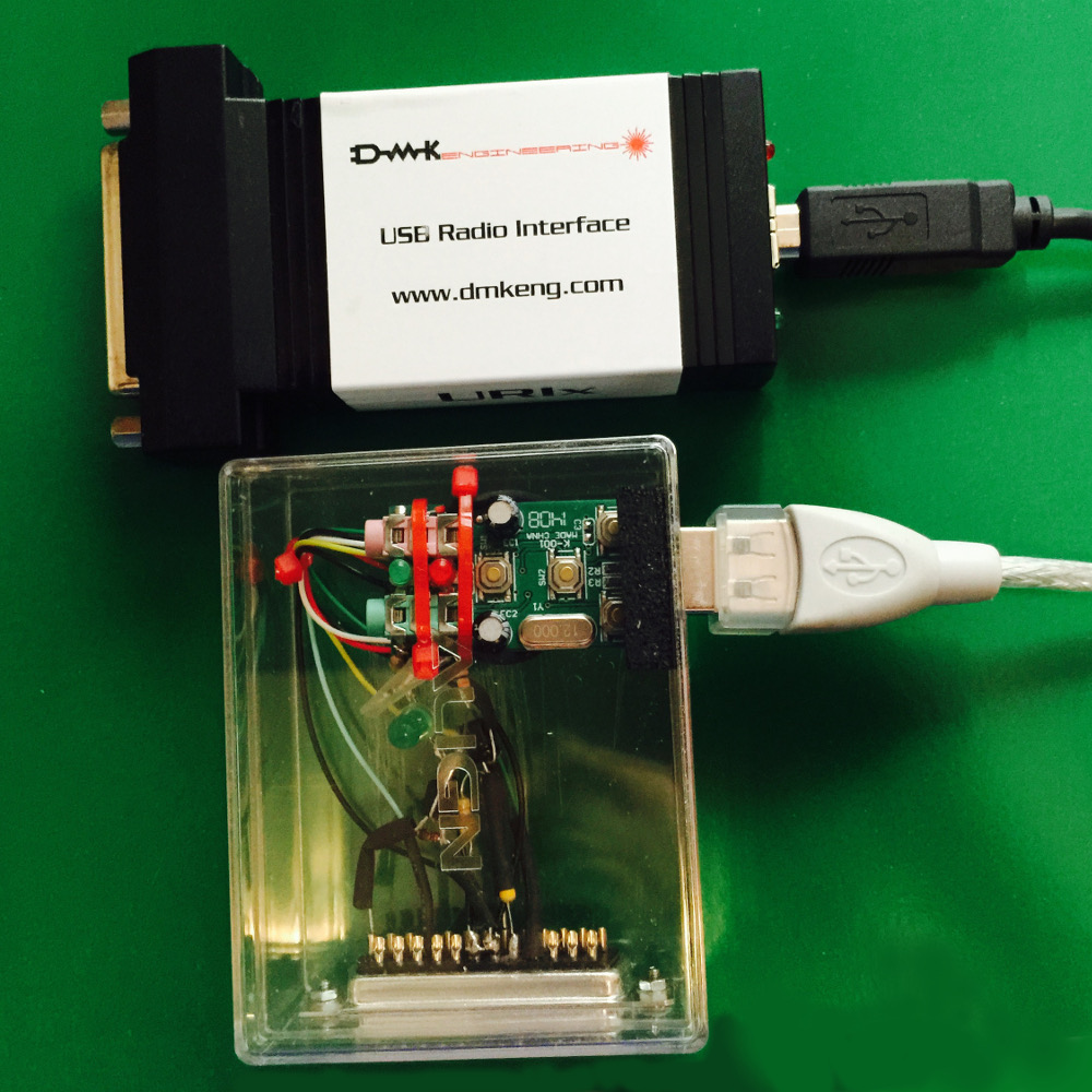
You need to decide how you want to assemble the far end of the adapter where the parts go. I chose to use a female DB25 wired to mate with the male DB25 that normally goes to a DMK-URI. This makes it easy to switch between the two. If you don't already have a DMK-URI and cables then you may choose to use a different approach. Perhaps a small perf board and box with in and out cables. The idea here is minimize what you need to do to the FOB directly. So for the purpose of this article I will use a female DB25 wired like the DMK-URI connected by a short cable to the USB FOB.
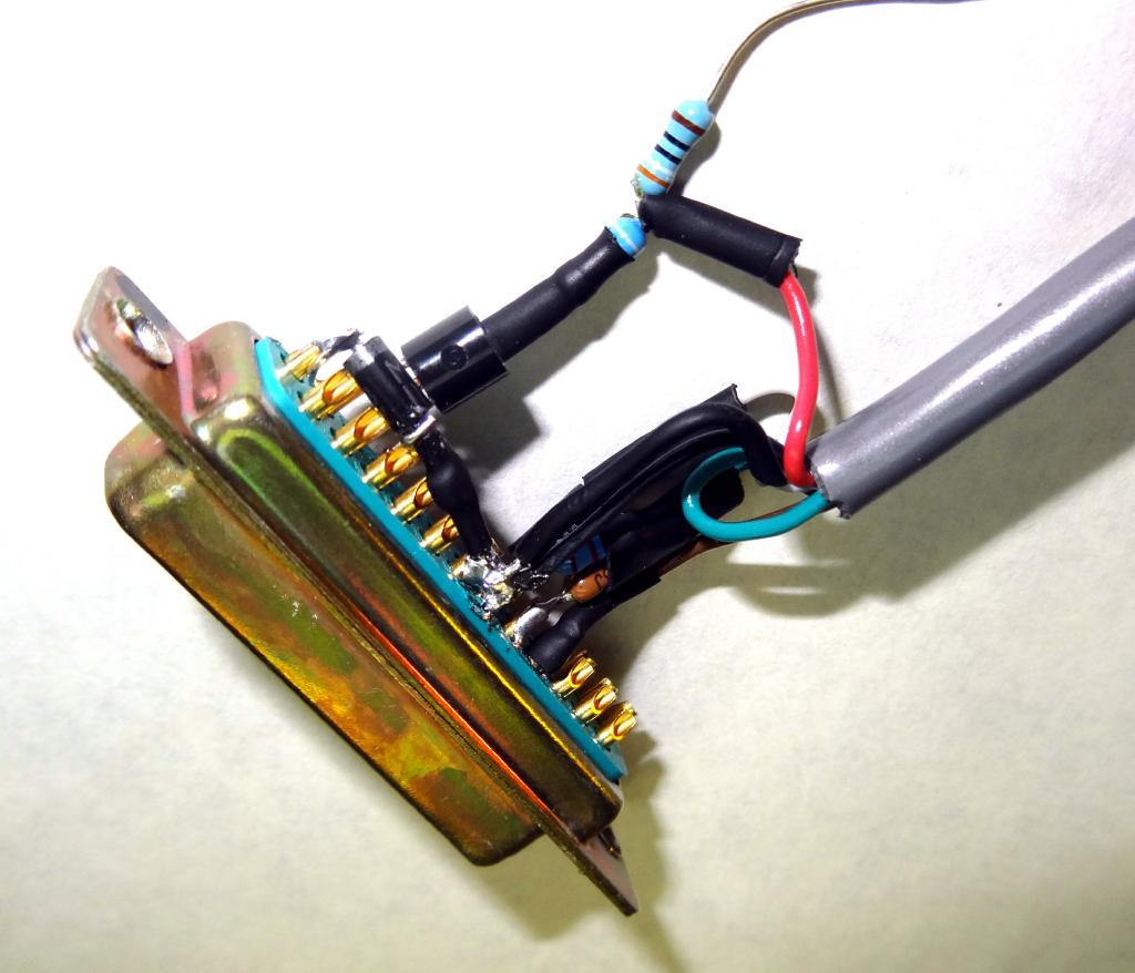
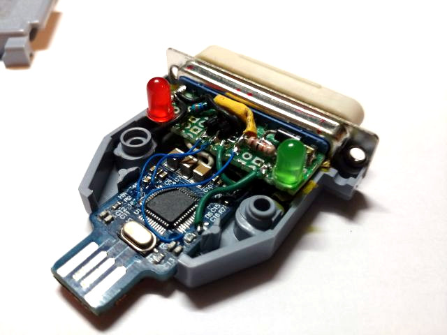
Now we will go on to prepare the DB25 shell. A PTT LED is optional. If you would like to have one you can add it into the shell by drilling a hole and securing it with silicone sealant. Connect short lengths of wire-wrap wire to the leads and mark the positive lead. This lead goes to the resistor and the negative lead goes to ground. I also drilled two holes for securing the cable with a tywrap but your method of securing may differ.
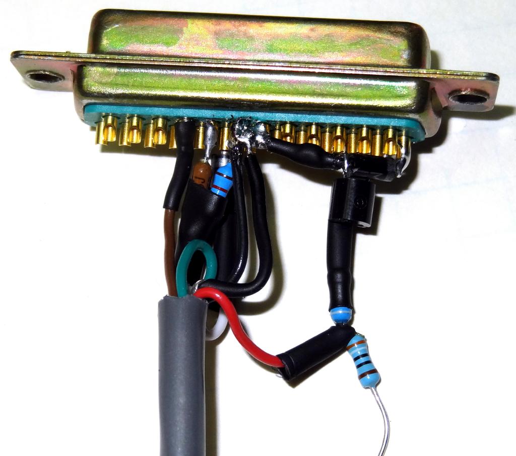
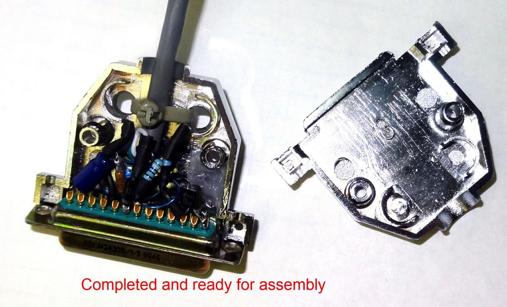
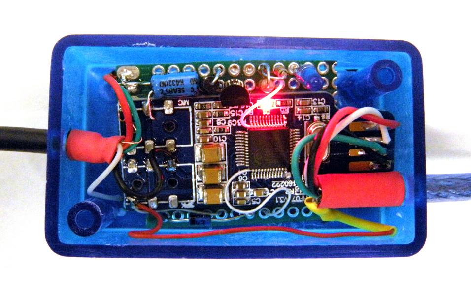
All of the components are mounted at the DB25 pins and contained within the shell. It is a little hard to see all the components in these photos but follow the schematic. When connecting remember that the pins on the connector go to the radio, the wires from the cable go to the FOB. I used a 2N7000 FET for PTT but you could use a bipolar device like a 2N3904. It just has to handle the keying voltage and current of your rig. Most modern rigs key with 12V or less and very low current but keep in mind there are some older rigs and commercial equipment that might require different ratings. When using the DMK-URI wiring scheme I always wire pin 19 and 20 together. They are both ground and some might just use one or the other and if you happen to use the wrong one you won't have a ground. Wiring them together avoids that problem.
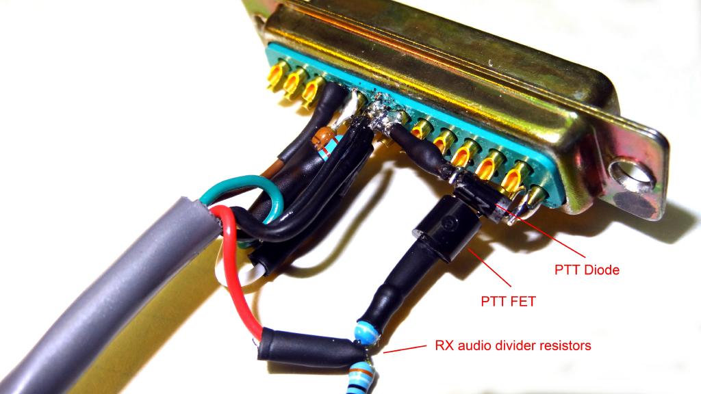
Please note there is a label error in the above photo.
The junction of the two resistors shown with red lead is the PTT line not the audio divider.
One resistor drives the FET and the other the PTT LED mounted in the shell.
Once completed the shell can be assembled and the tested. Operation should be similar to the DMK-URI as far a configuration and level settings are concerned. Since levels can vary on these FOBS you might want to adjust the resistor values to match what you had with the DMK-URI or bring a particular radio near the middle (500) of the level range for Allstar.
Another method to connect COS and PTT to the CM108
Dave, KB4FXC submitted these photos of a method he suggests for attaching the wires. The small wirewrap wires are inserted under the pins from the opposite end. The stripped end is then wrapped around the connection pin and soldered. This makes it easy for those who may not be able to hold the wire and the iron steadily to tack the wires on as shown in the above example. In either case the board should be secured in a vise so it does not move and you should use a magnifier. Putting the wires under the pin acts as a strain relief so no silicone should be needed. This is not hard to do!
Wires are fed under the leads to opposite end.
Stripped end is wrapped over pin. Only strip enough to go
around the pin. Don't let it touch the adjacent pin.
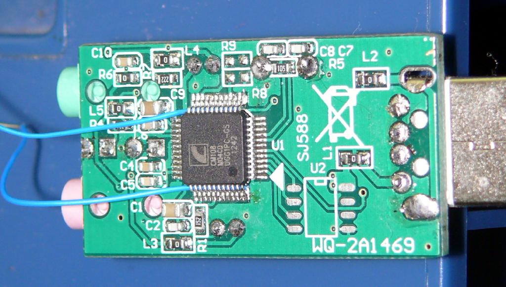
Quickly solder. This does not require much time! Tin the iron and touch it to the pin.
User built Interfaces

Here is an example FOB modification by John N8QHI
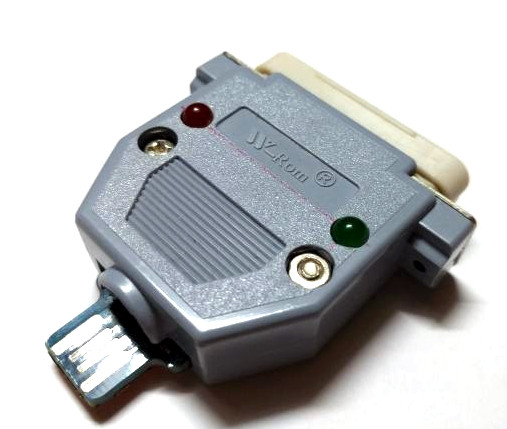
A FOB mod by VR2XKP using the newer "caseless" FOB mounted in a DB25 shell
A FOB design by WB3DZZ. These modified FOBS with DB25 DMK/URI pinout are available for purchase.
Contact WB3DZZ via his QRZ email address.
Further Information
The FOBS listed below can be modified as of Summer 2016
- https://www.amazon.com/gp/product/B001MSS6CS/ref=oh_aui_detailpage_o03_s01?ie=UTF8&psc=1
- http://www.newegg.com/Product/Product.aspx?Item=N82E16812186035&cm_re=syba_usb-_-12-186-035-_-Product
- http://www.ebay.com/itm/272374780193 - Latest FOB - No case and no blob!
- Simplified schematic used in this project
A note about FOBS
As of the beginning of 2016 it has become increasingly hard to find sound FOBS without potted electronics that allow the above modifications. The above links while not the only possible choices have not shown up potted and it is a smaller footprint FOB allowing for use in a tighter physical installation. The "caseless" FOB that has appeared in 2017 is probably the best choice. It is a good quality board and easier to modify.
Conclusion
I hope this article makes modifying a sound FOB a little easier for you. Jump in and try it. At $3 and change it is not a big loss if you screw a couple up! As always have fun and happy hamming.
© 2015, 2016, 2017 - WA3DSP